NFPA Panel
The NFPA panel allows the user to enable NFPA settings, set the Hazen Williams factor, and define an ambient pressure for NFPA calculations.
NFPA stands for the National Fire Protection Association. This association develops codes and standards that are used by engineers designing safety related systems related to fire protection. AFT Fathom provides users the ability to specify remote paths and automatically calculate the hydraulics through that path as is recommended in the NFPA 15 standard 8.5.3.1 (NFPA 15 2012NFPA 15, Standard for Water Spray Fixed Systems for Fire Protection, 2012 Edition., 23). When coupled with the GSC module (Goal Seek and Control), AFT Fathom includes the ability to determine the hydraulically most remote path automatically.
NFPA Calculations Tutorial
To enable the NFPA calculations, they must first be enabled in Analysis Setup. From the AFT Fathom Workspace, open the Analysis Setup window from the toolbar. In the Miscellaneous group on the left select the NFPA panel. Check the box next to Enable NFPA. By default, the Hazen Williams value is set to 120 and the ambient pressure is equal to 1 atm. You have the ability to change these initial values if you would like. See Figure 1 for this window.
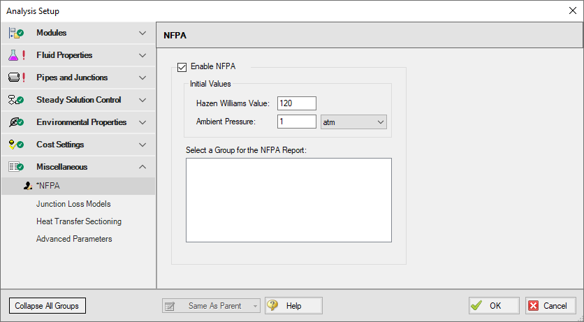
Figure 1: Enabling NFPA Calculations in Analysis Setup
Because NFPA calculations are performed using equivalent lengths to determine hydraulic loss, AFT Fathom allows the user to model all fittings losses using this method. To enable this feature, go to the Junction Loss Models panel (also located in the Miscellaneous group of Analysis Setup) and select the radio button to “Include Equivalent Lengths” and then select your unit preference (see Figure 2). Note that fittings & losses must be modeled with equivalent lengths in order for the F parameter (equivalent length due to fittings) in the NFPA output report to be displayed correctly. If fittings are modeled any other way, the pressures and flows calculated by AFT Fathom will still be correct, but the equivalent length due to fittings will show as 0, even if there are fittings in the pipe.
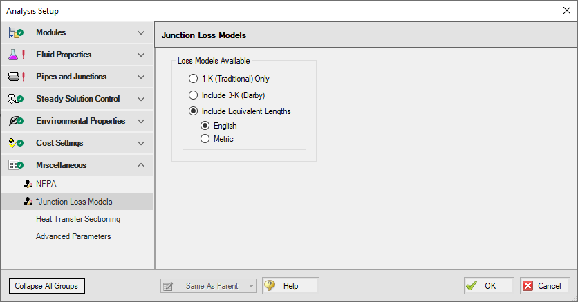
Figure 2: The Junction Loss Models panel in Analysis Setup with Equivalent Lengths enabled
After NFPA has been enabled, check that NFPA calculations are set to be used. To do this, open the Analysis menu, select “NFPA Configuration”, and then select “Use” as shown in Figure 3.
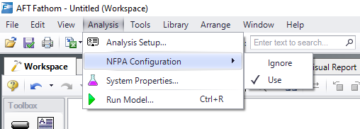
Figure 3: Specifying the use of NFPA on the Analysis tab
At this point, the model can be built and then set up to perform the NFPA calculations.
Once the model is built, you will need to create one or more groups in AFT Fathom so that it can generate the NFPA Report. Note that a group represents the pipeline path for which you would like to show the hydraulic calculations. See the discussion on Groups in AFT Fathom for more information on how to do this.
Note that an NFPA group must consist of a continuous path of pipes with a spray junction. Most commonly, per 8.5.3.1 (NFPA 15 2012NFPA 15, Standard for Water Spray Fixed Systems for Fire Protection, 2012 Edition., 23), the path will include all junctions from the water supply to the hydraulically remote spray nozzle. However, AFT Fathom will generate an NFPA report for all pipes and junctions in a group up to the downstream-most spray nozzle, regardless of whether this is the most hydraulically remote. This concept of defining groups is illustrated in Figures 4 and 5.
In Figure 4, only one pipe path is selected in red from Junctions J1 to J229 (i.e. if all pipes not included in this group were deleted, the flowing fluid would have only one path to flow through from junctions J1 to J229 with no branching pipes and no gaps between selected objects).
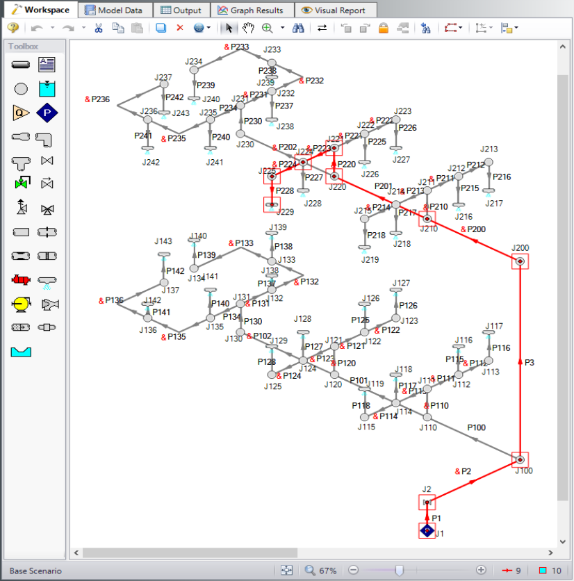
Figure 4: Example of NFPA group in AFT Fathom - note that all pipes and junctions in the flow path from J1 to J229 are included with all other branching pipes and junctions excluded
Figure 5 is an example of an incompletely defined NFPA group. In this figure, all pipes and junctions except Spray Nozzle J229 are included in the group. In this case, AFT Fathom will stop its NFPA Report at Spray Nozzle S3.
The NFPA Report generated in AFT Fathom will divide the hydraulic calculations as is done in the sample calculation in NFPA 15-53 (2012), with the equivalent pipe length for a given junction corresponding to the fittings plus pipe length in the pipe immediately upstream of that junction.
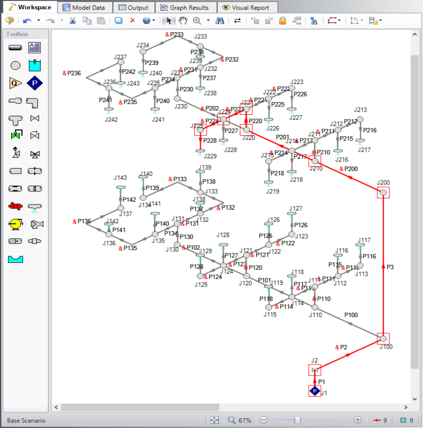
Figure 5: Example of NFPA group in AFT Fathom with Spray Nozzle J229 not selected
After the appropriate group(s) have been defined in your model, you must specify which path you would like to generate the NFPA Report. Note that an NFPA Report can be generated for only one group at a time. To specify this group, return to the NFPA panel in the Analysis Setup window. The NFPA groups created for the model will now be shown similar to Figure 6.
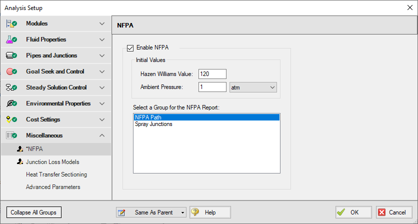
Figure 6: Select NFPA Group in the NFPA panel
Select the appropriate group and click Ok. Run the model and go to the Output window to access the NFPA Report. This report is shown in the General Data section under the NFPA Report tab as shown in Figure 7.
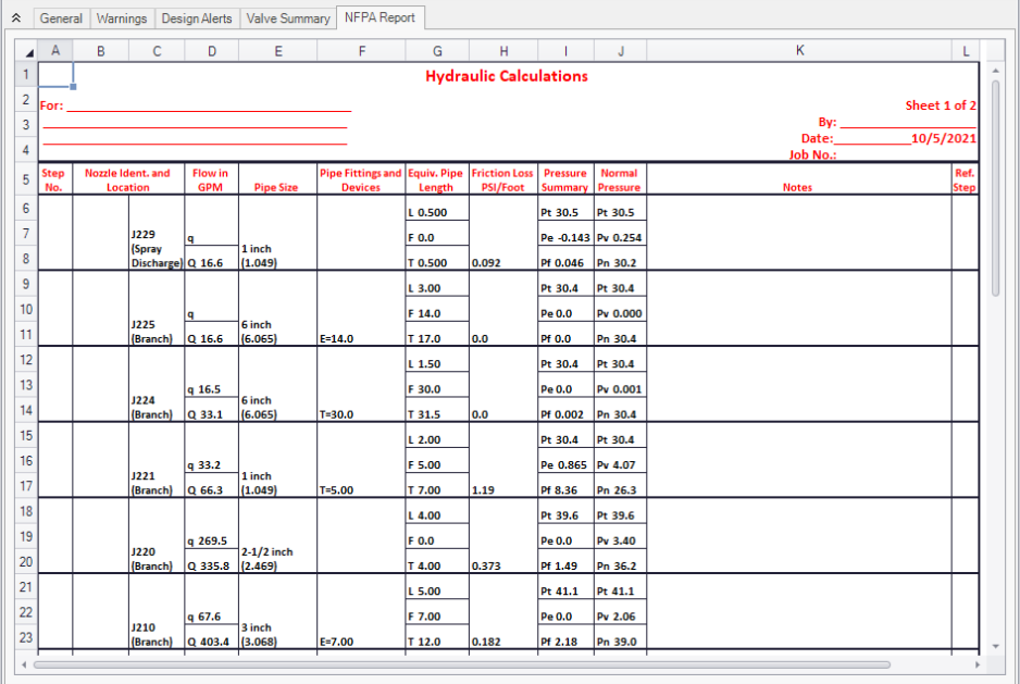
Figure 7: NFPA Report in the Output window in the General Data Section
Note that flow corrections are not made as AFT Fathom always takes into account the velocity pressure (also known as PV). Unlike the approximations in the NFPA codes 13 and 15 that are designed to calculate flow rates and system pressures by hand, the flows depicted in the NFPA Report are calculated by iterating until several fundamental flow calculations agree with each other, making corrections per the NFPA codes unnecessary when reporting the flow rates.
Using GSC to Determine the Hydraulically Most Remote Nozzle
If you have the GSC (Goal Seek and Control) add-on module to AFT Fathom, determining the minimum supply pressure needed to ensure that the hydraulically most remote nozzle receives sufficient flow can be automated. AFT Fathom will even report which nozzle is the hydraulically most remote.
To set this up, first enable GSC in the Modules panel, then create a group that contains all the spray nozzles in your system. Once this group has been formed, open the Variables panel in Analysis Setup and set your supply pressure as the variable. On the Goals panel define a Group Goal as the Goal Type and set the Object Type to Group Max/Min with a Volumetric Flow Rate goal parameter of greater than or equal to the minimum required flow through the spray nozzles.
In the example in Figure 8, the supply pressure is modeled with J1, so this is the parameter that is varied. In this same example in Figure 9, the minimum required flow is 42 gpm, so this is what the Goal Value is specified as in the Goals panel.
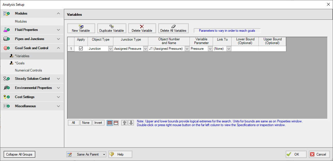
Figure 8: Variables panel in Analysis Setup with J1 specified as the parameter to be varied
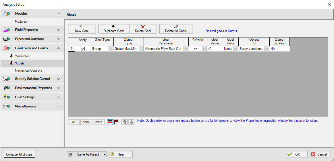
Figure 9: Goals panel in Analysis Setup with a goal of a minimum flow through each spray nozzle of 42 gpm
Once these parameters have been defined, run your model and check the GSC Variables and Goals in the general data section in the Output. Note that the output specifies an Object Used for Group Goal, which will be the spray nozzle that receives the minimum flow, or the hydraulically remote spray nozzle. In this example, J227 is the hydraulically remote spray nozzle (see Figure 11).
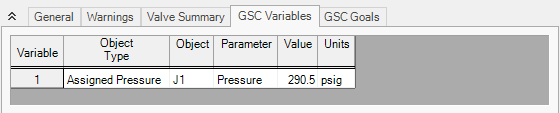
Figure 10: GSC Output with necessary supply pressure to achieve minimum flow through hydraulically remote nozzle
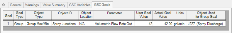
Figure 11: GSC Output with Spray Nozzle that contains Hydraulically Most Remote Nozzle
Related Blogs


