Reference Density
A relationship can be drawn for many components between flow energy and flow rate. This can be a decrease (e.g., a loss across a valve) or increase in energy (e.g. energy added by a pump). The specific parameter used to represent flow energy can vary depending on application. It can be given in terms of pressure change or head change, and there is a critical difference between the two.
Consider a centifugal turbomachine (a pump or radial compressor): Kinetic energy is imparted to the fluid by accelerating it along the radius of the impeller. If the rate of rotation is held constant, a denser fluid will have more energy imparted to it than a lighter weight fluid. This would give rise to higher pressures. In other words, the pressure change depends on the density of the fluid.
Pump curves are generally provided in terms of head. This is convenient because head is a unit of specific energy - or energy per weight. Therefore, it does not vary with fluid density like pressure does. The head added to a fluid by a pump at a fixed speed, for example, will be the same for water and liquid mercury.
However, head relationships are not always available or meaningful. If a pressure vs flow relationship is used, a reference density must be specified. This is the fluid density used during testing and creation of the curve.
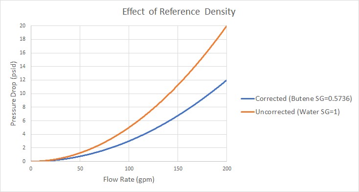
Figure 1: Visual comparison of Pressure Loss Curves for differing densities. Head curves would be identical for this component
Affected Parameters
There are several parameters that are affected by the density of the fluid:
-
Pressure - As discussed above
-
Mass Flow - The mass term contains information about the density of the fluid
-
Power - More power is demanded by a pump to meet the head curve for a denser fluid. While head is independent of density and therefore often reported by manufacturers, power is not independent of density. Therefore, a proper specification sheet that includes power must also include the reference fluid density.
Accounting for Reference Density
Pumps and Resistance Curves allow for the specification of a reference density if one of the above parameters is selected. The selection appears below the curve fit area as shown in Figure 2.

Figure 2: Reference Density Selection
There are three options:
-
No Correction (default) - This selection assumes that the component was tested with the fluid defined in Analysis Setup on the Fluid panel.
-
Water @STP - This selection assumes the reference density - the density of the test fluid - is that of water at standard temperature and pressure. If the System Property fluid differs, the entered curve will be corrected.
-
User Specified - This directly specifies the reference density. If the System Property fluid differs, the entered curve will be corrected.


