Sectioning Panel
Before running a transient simulation, the pipes must be sectioned as described in Pipe Sectioning - Introduction to Method of Characteristics. This forces a common time step, and forces the section length to be equal to the product of the pipe wavespeed and time step. The Sectioning panel controls how the pipes are sectioned.
Sectioning is a required item in the Analysis Setup window when transient simulation is enabled.
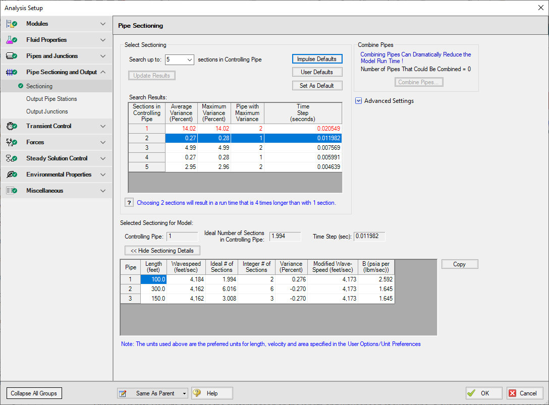
Figure 1: The Sectioning panel
This window automates the selection of an appropriate sectioning scheme for a particular model.
Clicking Update Results analyzes the system based on the length and wavespeed of every pipe. The sectioning window automatically selects the lowest number of sections in the controlling pipe that will produce a Maximum Variance below the accepted amount. This accepted amount defaults to 10%, but can be changed as discussed below in Sectioning Options. The meaning of Variance is discussed in Pipe Sectioning - Introduction to Method of Characteristics.
The Selected Sectioning for Model area shows the effects of the currently selected sectioning on the controlling pipe, as well as the overall time step required.
Note: Be careful when selecting the number of sections. The run time required increases with the number of sections squared, so the number of sections should be minimized where possible. There is not a direct correlation between number of sections and accuracy of results. It is not good practice to increase the number of sections to obtain more accurate results. For large models it may be wise to accept additional variance for the decrease in run time, at least for preliminary runs.
Sectioning Options
-
Search up to X sections in Controlling Pipe - the number of sectioning options to search up to can be defined here. This can help prevent unnecessary searching in large models, or allow additional sections in models where it is required.
-
Combine Pipes - The Combine Pipes utility is accessible here. Combining Pipes can greatly reduce model run time in many cases. See Minor Wave Reflections.
-
Advanced Settings
-
Show Detailed Searching Options - This allows for searching a certain range. This is useful if you do not want to spend time searching for low numbers of sections when it is already known that these are unacceptable.
-
Maximum Allowable Variance - This has no effect on the model, it only affects which rows are deemed unacceptable (colored red) and which entry is automatically selected.
-
Search Options
-
Bandwidth - How far away from the specified number of sections should be searched.
-
Increment - How many individual points should be tested. The searching algorithm will check all of the pipes for all combinations in a 2*Bandwidth range at Increment intervals. Small Increment and large Bandwidth could potentially find a better result at the cost of computational time.
-
-
Show Sectioning Details - This shows the resulting number of sections, variance, and other information about every pipe in the model for the selected sectioning.
Numbering Convention for Pipe Sectioning
Once a pipe is broken into sections, computation takes place where the sections join together. These are called pipe stations. The total number of stations in a pipe is equal to the number of sections plus 1. The station at the beginning of the pipe is numbered zero.
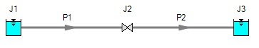
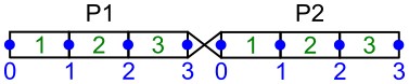
Figure 1: Computing Stations (blue) exist at the boundary of every section (green)
To observe parameters at the inlet or outlet of a junction, view the station adjoining the junction. In the above example, the inlet to the valve is P1, Station 3 and the outlet is P2, Station 0.


