Sectioning Panel with PFA Module
(PFA module only) In AFT Impulse (with or without the PFA module), the pipes are sectioned in order to comply with the Method of Characteristics. You can read about pipe sectioning in the Method of Characteristics Pipe Sectioning topic. Essentially, the pipe with the smallest L/a value is the controlling pipe, and the maximum time step will be equal to Equation 1.
|
|
(1) |

In the traditional AFT Impulse, the Sectioning panel will display from one section in the controlling pipe (that is, the pipe with the least number of sections) to the specified number of sections in the controlling pipe.
However, in the PFA module, the pipe sectioning must be further refined to prevent any number of pipe sections in the controlling pipe that results in a time step larger than the Maximum Time Step Based on Cutoff Frequency, which is calculated using Equation 2.
|
|
(2) |

Figure 1 shows the modified Sectioning panel that is used in the PFA module.
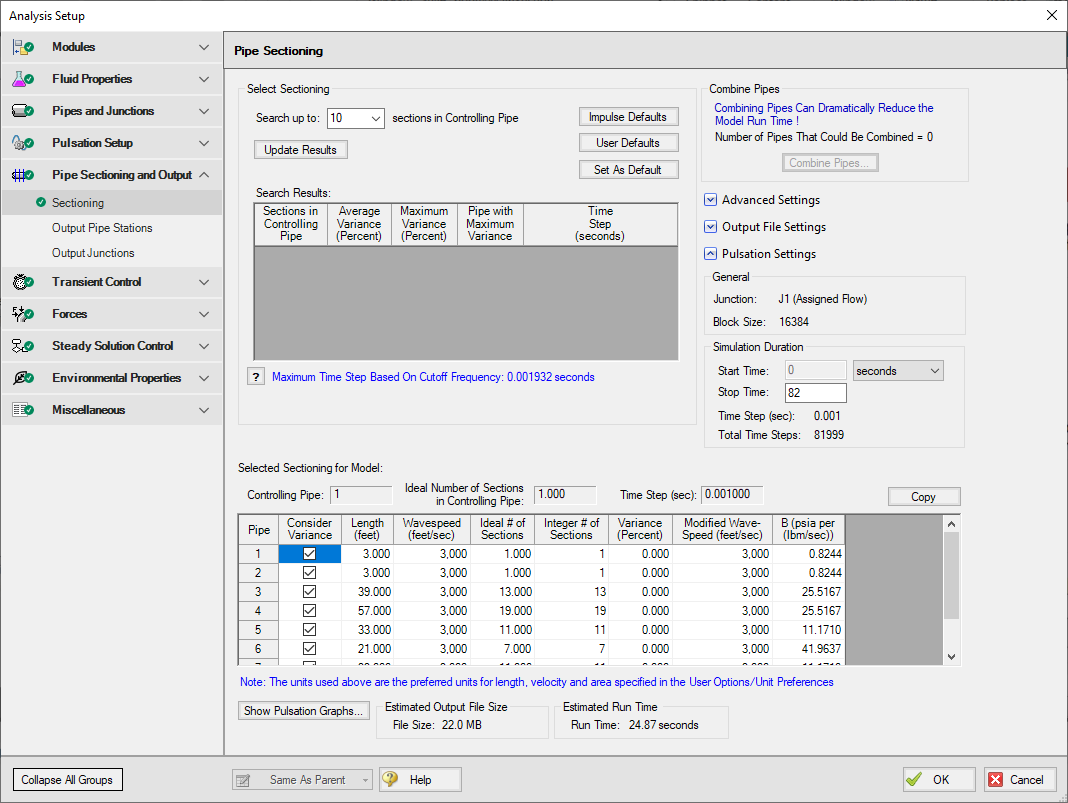
Figure 1: Sectioning panel in the PFA Module
In Figure 1, this example shows that the when the controlling pipe has one section, the time step is still large enough for the Cutoff Frequency. However, if the Maximum Time Step Based on Cutoff Frequency was larger than the 0.001 seconds shown here, the option for one section in the controlling pipe would not be shown. Note that the number of sections in the controlling pipe can drastically affect the model run times, so it is recommended to select the smallest amount of sections in the controlling pipe as possible.
A feature unique to the PFA module in the Sectioning panel is the ability to exclude certain pipes in the sectioning variance or modification calculations. This allows the user to use pipes to model dampeners or devices that are not strictly a pipe. To exclude certain pipes from the sectioning calculations, ensure that the box next to the pipe in the Sectioning panel is unselected. These pipes will still be sectioned based on time step.
The Pulsation Settings section of the Sectioning panel automatically calculates the Block Size based on Equation 3.
|
|
(3) |

The Sectioning panel allows you to specify the Simulation Duration. The minimum required Simulation Duration is automatically calculated.
Note: The Simulation Duration and Output File Setting inputs are located on the Simulation Mode/Duration panel when the PFA module is not activated.
Once the sectioning has been completed, click on the Show Pulsation Graphs icon on the bottom of the Sectioning panel to see graphs of the Pulse, the FFT of the Pulse, the LPF of the Pulse, and the FFT of the LPF. Close out of the graphs, and then click OK to accept the pipe sectioning.
When you exit the Sectioning panel after fully defining the sectioning, a message appears informing you that the PFA module will now place the forcing function onto the junction you selected as transient data. Click OK. You will notice that the forcing function has now been input in the specified junction Properties window on the Transient data tab.
Note: If the forcing function is being added to a pump junction the pump must be defined as a positive displacement pump with a steady flow rate. This requirement is in place to avoid artificial transients in the system.
Related Topics
Pipe Sectioning - Introduction to Method of Characteristics
PFA - Pulsation Frequency Analysis
Steady-State Pulsation Tolerance
Related Examples


