Surge Tank
The Surge Tank junction allows up to twenty-five connecting pipes. This junction type is useful for modeling a small open tank vessel designed as a surge protection device (see Figure 1). The Surge Tank may be integral with the pipe system, separated by an orifice, or by a short connector pipe.
The Surge Tank Properties window follows the second of the two basic Properties window formats. A table on the Pipes tab displays the connecting pipe information, including flow direction and loss values. The table grows in size to accommodate up to twenty-five connecting pipes.
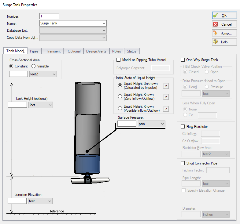
Figure 1: Surge Tank Properties Window
Tank Geometry
The Tank Height is the physical top of the tank in relation to the elevation. If there is a Connector Pipe, then the Tank Height is relative to the top of the Connector Pipe. This height is used in the case of overflow. If the surge tank overflows, spillage will occur and the liquid will exit the pipe system not to be recovered. If you do not want to model the overflow, specify a very tall tank or do not enter a Tank Height.
If the Tank Cross-Sectional Area is specified as Constant, the surge tank is assumed to be a vertical tank with constant cross-sectional area. If the tank cross-sectional area changes with height, this can be entered by selecting the variable option and entering the cross-sectional variation in the table.
The Tank Cross-Sectional Area is used for the purpose of determining the liquid volume. It will determine how high the liquid will rise or drop, since a given volume of liquid will flow into the tank during a time step.
Initial State of Liquid Height
The Initial State of Liquid Height must be defined based on the application of the surge tank. There are three available options.
-
Liquid Height Unknown (Calculated by Impulse) - This is the default option which allows Impulse to calculate the liquid height based on the static head at the junction, and is typical for most applications. During the transient, flow will go in and out of the tank, and the liquid level will change.
-
Liquid Height Known (Zero Inflow/Outflow) - This option allows the surge tank to act as a pressurizer, similar to a reservoir junction. In this case it is assumed that the surge tank is acting as a reference pressure for a closed loop, in which no inflow/outflow is possible in the steady state. The defined initial liquid height in the tank will be converted to a reference pressure. During the transient, flow will go in and out of the tank, and the liquid level will change.
-
Liquid Height Known (Possible Inflow/Outflow) - This option again allows the surge tank to act as a pressurizer. In this case it is assumed that the surge tank is providing a reference pressure for an open system, in which steady state inflow/outflow would be possible. The defined initial liquid height in the tank will be converted to a reference pressure. During the transient, flow will go in and out of the tank, and the liquid level will change. This option is similar to using the Finite Open tank model in the Reservoir junction.
Interface with Pipe System
The Surge Tank can connect into the pipe system in three ways: it can be integral with the pipe, it can be separated by an orifice, or it can be connected by a short pipe.
These options are provided in the Flow Restrictor and Connector Pipe areas. If neither option is used, the surge tank is assumed to be attached directly to the pipe with no hydraulic loss.
If the Flow Restrictor is used, the surge tank is assumed to be separated from the pipe system by an orifice, which causes an hydraulic loss as the liquid flows in and out of the surge tank. The loss is specified by entering a flow area and discharge coefficient. Further, this loss can be different for inflow vs. outflow.
Lastly, the surge tank can be connected by a short pipe which is considered to be short in relation to the other pipes in the system after they are sectioned. If the pipe is short, it can be assumed to react instantaneously with the surge tank. The short pipe accounts for liquid inertia and friction. If a connector pipe exists which cannot be considered short, it should be modeled as an actual AFT Impulse pipe.
The Flow Restrictor and Connector Pipe can both exist in the same surge tank. That is, a flow restrictor can be modeled at the top of a connector pipe, and the effect of both will be included.
One drawback of surge tanks is that they must be located in low pressure parts of the system because high pressure locations require a very tall surge tank (a water surge tank located where the pipe system is at 100 psig must have a liquid surface at least 230 feet higher than the pipe), unless there is a check valve connecting the surge tank to the pipe. Since the tank can only flow out, it is only useful to limit low transient pressures by flowing liquid into the system when the pressure drops. However, when the pressure rises, the check valve closes and the tank cannot accept any fluid and thus decrease the system pressure.
Such a design is called a One-Way Surge Tank, and it can be modeled by clicking the check box next to One-Way Surge Tank on the Tank Model Tab, then defining the check valve characteristics and initial liquid height which subsequently become active.
A dipping tube vessel is a combination surge tank and gas accumulator (see Figure 2). As long as the liquid level remains below the Height at Tube Bottom as shown in Figure 2, it acts like a conventional surge tank. If the liquid level rises above the bottom of the tube,gas gets trapped in the upper region and the device acts like a gas accumulator.
The dipper tube capability can be enabled by checking the box on the Tank Model tab, which will update the window with the required additional inputs of polytropic constant, height at tube bottom, and tank height.
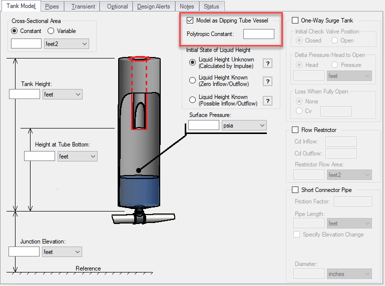
Figure 2: Dipping tube vessel geometric representation. When the liquid level rises above the height of the tube bottom, it acts like a gas accumulator
Transient Data
On the transient data tab the surface pressure can be varied with time to simulate a tank pressurization. For more information on transient data, including event transients, see Junction Transient Data.
Special Condition
The special condition for the Surge Tank on the optional tab allows the user to set Impulse to ignore the surge tank. See Special Conditions for more information.
Graphing Surge Tank Data
You can track the surge tank flowrate, total mass or volume, and liquid surface level pressure by selecting these options in the Output Junctions panel of the Pipe Sectioning and Output group. These parameters can be graphed or reviewed in the Output window.


