K Factor Loss Model
AFT xStream models component losses according to the following equation:
|
|
(1) |

where K is commonly referred to as the loss factor. Note that for calculation purposes this pressure loss is a stagnation pressure loss.
Table 1 lists the sources for the k factor loss models used in AFT xStream. The losses implemented directly in the code were chosen on the basis of ease of use. Many loss factor types are functions of the flow, and thus too general to be easily incorporated.
Table 1: Loss model references
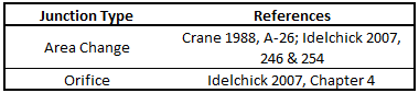
Crane (1988)Crane Co., Flow of Fluids Through Valves, Fittings, and Pipe, Technical Paper No. 410, Crane Co., Joliet, IL, 1988. offers good general purpose correlations for modeling irrecoverable losses in pipe systems. A well prepared pipe flow analyst would be advised to have copies of either or both of these references.
Another lesser known source of loss factor information is Idelchik's Handbook of Hydraulic Resistance (Idelchik 2007 Idelchik, I. E., Handbook of Hydraulic Resistance, 4th edition, CRC Press, Boca Raton, FL, 2007. ). This reference is indispensable for the engineer who must make detailed assessments of pipe systems in which so-called minor losses play a significant roll. The reference is voluminous in scope and full of tables, charts and equations for calculating loss factors for almost any pipe arrangement.
Miller 1990Miller, D. S., Internal Flow Systems, 2nd edition, Gulf Publishing Company, Houston, TX, 1990. is another reference offering good general purpose hydraulic data.
K Factor Losses in Compressible Flow
Most handbook K factor data is based on incompressible flow tests or theory. Applying standard K factors to compressible flow components carries some uncertainty. There are not any universally accepted methods available to determine K factors for truly compressible flow except in very specific situations.
xStream offers common handbook values for K factors, and you should use caution in how you apply the data. Also recognize that when you use the “Fittings & Losses" in pipes, computationally these K factors are spread out along the whole pipe as distributed losses. In compressible flow, the location of a fitting along a pipe will affect the actual pressure loss since velocity is not constant along a pipe. The Fittings & Losses do not account for this.
Transient Theory
When a junction is defined using a K factor, the junction inlet will be treated as a static pressure boundary. A guess for the inlet static pressure is made, which can be used to solve for the inflow conditions using the compatibility equations as shown for the Assigned Pressure junction at the downstream end of a pipe. With the known inlet conditions, the inlet stagnation pressure and stagnation enthalpy can be calculated and used to solve for outlet stagnation pressure using the K factor loss equation above.
With the outlet stagnation pressure and enthalpy the outlet conditions can be solved using the method for an assigned pressure boundary.
With both the inlet and outlet conditions known the inlet and outlet mass flow rates can be calculated and compared. If the mass flow rate difference is too large, then iterations on the inlet static pressure will be completed until the mass flow rate tolerance is met.
Exit Junction Transient Theory
If a K factor loss is defined for a junction that is specified as an exit type junction, such as a relief valve, then a different solution method must be applied as there is no downstream pipe.
The user specified exit conditions are assumed to be stagnation properties. The K factor loss model can be rearranged and the compatibility equations substituted as follows.


The combined equations can then be rearranged to solve for velocity and density at the junction inlet.
If flow reverses at the exit junction then the solution will be similar to the solution with two pipes connected, except that the effective pipe area at the exit side of the junction will be assumed to be equivalent to the area of the pipe connected to the entrance of the junction.
Sonic Choking Transient Theory
Either restriction choking or expansion choking can occur at junctions modeled with K factor loss, depending on the geometry of the junction.
When the flow is choked iterations on the inlet pressure will be performed similar to the non-choked transient solution. However, the sonic area will be used as the dependent variable for the iterations. Once the inlet conditions are determined, the mass flow rate and stagnation enthalpy can be used to solve for the outlet conditions.