Importing Piping Component Files
AFT Arrow includes the ability to import Piping Component Files (.pcf), which can be generated by a wide range of software, and provide a quick way to get started with the hydraulic modeling portion of a project. Files can be imported into existing models.
Selecting File > Import Piping Layout From > Piping Component File (.pcf) brings up the Import Piping Layout Wizard in the Quick Access Panel, as shown below in Figure 1.
The Import Piping Layout Wizard is organized into sections that help guide the import process:
-
Folder Browser - After browsing to a folder, all .pcf files within the folder will be listed here. Simply clicking a file in the list will show a preview of the import in the Workspace. The location of the preview can be moved by dragging the icon in the upper-left of the selection area.
-
Object List - When a file is selected, the objects to be created will be listed here. Each individual object can be reassigned to a certain Junction, if the automatic assignment is not correct. For example, the originating software may have only had a "valve" while this could be a Relief Valve or a Control Valve. Changing the AFT Object type will change the preview in the Workspace. Right-clicking on an object shows a menu for converting object types.
-
Property Window - This button opens an additional panel that shows the raw properties for the currently selected object.
-
Link Materials - Opens the File Object Link window, where the Materials Codes from the pcf file can be associated with a pipe material, size, and type in the AFT Pipe Material library. The selection from the AFT Pipe Material library will overwrite any diameter information from the pcf file. Selections made for a pcf material will be applied to all pipes that reference that pcf material. Pipes associated with each material can be seen by clicking the arrow on the left expand the group (Figure 2).
-
Show Ignored Objects - Certain types of objects are ignored on import - these can be objects such as flanges, or additional file components such as materials or bolt specifications.
-
-
Options
-
Min Pipe/Max Pipe - Information fields on the length of the shortest pipe and longest pipe in the list of pipes to be imported.
-
Ignore Pipes of Length Less Than - Do not import pipes shorter than this amount.
-
Ignore Pipes of Diameter Less Than - Do not import pipes smaller than this diameter.
-
Ignored Pipes - How many pipes will be ignored based on the above settings. Ignoring pipes can be helpful in keeping a model clean and free of unnecessary components. For example, a pipe stress software may require many short pipe segments in between welds or flanges. However, these types of connections are almost always ignored for hydraulic analysis. By ignoring short pipes, the amount of "import clean up" required can be reduced.
-
Preferred Scale - The wizard will Auto Scale the import by default. If a different scale is desired, this option can be disabled and a custom scale entered.
-
Show Pipes in Preview - Display the pipes in the Workspace preview.
-
Show Junctions in Preview - Display the junctions in the Workspace preview.
-
Combine Pipes When Possible - It is required that all pipes in the Workspace be connected by two junctions. However, this is not a requirement in all software. Therefore, some .pcf files may be generated with several pipes "end to end." If the pipes were imported this way, junctions would need to be added, or the pipes would need to be manually combined, before the model could be solved.
-
Import Bends as Pipes - Pipe bends can be considered as junctions or simply a visual change in direction of the pipe. This is identical to using segments to show piping layout. Note that these bends are visual only and have no losses associated with them - to account for losses, either junctions or fittings & losses must be used. This option is helpful to reduce unnecessary model clutter.
-
Ignore Fitting Lengths - Neglects additional length added to pipes that accounts for the equivalent length of fittings and losses, and is not actually part of the physical pipe length.
-
Import Data to Pipe or Junction Notes Field - Add the raw data from the originating file to the Notes tab of the corresponding object.
-
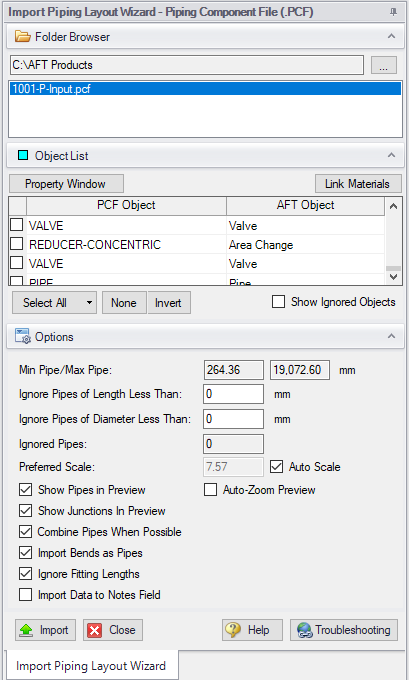
Figure 1: Piping Component File Import
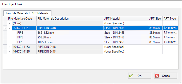
Figure 2: File Object Link window for Piping Component File Import
Related Topics
Importing CAESAR II Neutral Files
Importing and Exporting EPANET Files
Related Blogs


