Importing from Excel
A Microsoft Excel spreadsheet can be used to make changes to objects in an AFT Arrow model. The values in the Excel file are located in specific locations as described in the Setting Up Excel section.
Setting Up Excel
When reading an Excel file, AFT Arrow will search for a worksheet named "AFT Transfer". There can be other worksheets in the workbook, but AFT Arrow will only look for a sheet with this name. The file structure looks like the following:
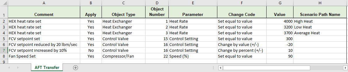
Figure 1: Sample AFT Transfer Excel Sheet
Row 1 and column A are not read by AFT Arrow - these cells can have any value in them, though it is recommended to enter the values above for the header row.
Each column has certain accepted values, which can depend on the values in neighboring columns.
Note: A template spreadsheet containing validation rules for the required layout is included in the AFT Arrow installation. By default the file path is: C:\AFT Products\AFT Arrow\AFT Arrow Excel Import Workbook.xlsx, or the spreadsheet can be downloaded here.
Apply Column
This column accepts Yes or No. Only changes marked as Yes will be imported into the model.
Object Type
This column must be a junction name or Pipe. Valid choices can be seen below in Table 1.
Object Number
This corresponds to the junction or pipe number.
Parameter
The specific parameter to be changed. These parameters vary based on the Object Name selected.
Table 1: Object Types, Associated Parameters, and Change Codes
|
Pipe S Additional K Factor S Ambient Fluid Velocity S Ambient Temperature S Buried Pipe Depth S Design Factor - Pipe Fittings & Losses S Design Factor - Pipe Friction S Design Factor - Pipe Heat Transfer S External Heat Flux/Tracing Flux S External Heat Rate S Initial Guess Flowrate S Inner Diameter (for unspecified, cylindrical pipes) S Length I Nominal Size Increment C Nominal Size Set (must match text in Pipe Property Window) C Nominal Type Set (must match text in Pipe Property Window) S Noncylindrical Flow Area S Noncylindrical Wetted Perimeter C Pipe Name S Rectangular Duct Height S Rectangular Duct Width S Roughness Value (for unspecified friction models) S ID Reduction (Scaling) I Sizing/Cost Setting S Soil Surface Temperature I Special Condition |
Area Change S CdA (for sonic choking) S Design Factor S Initial Guess Pressure S Initial Guess Temperature S Elevation C Junction Name I Sizing/Cost Setting S User Specified K |
Assigned Flow S Design Factor S Flow Rate S Initial Guess Pressure S Initial Guess Temperature S Elevation C Junction Name I Sizing/Cost Setting I Special Condition S Temperature (Static) |
Assigned Pressure S CdA S Design Factor S Elevation C Junction Name S Pressure I Sizing/Cost Setting S Temperature |
Bend S CdA (for sonic choking) S Design Factor S Initial Guess Pressure S Initial Guess Temperature S Elevation C Junction Name I Sizing/Cost Setting S User Specified K
|
|
Branch S Design Factor S Initial Guess Pressure S Initial Guess Temperature S Elevation C Junction Name I Sizing/Cost Setting S Source/Sink Flow S Source/Sink Temperature/Enthalpy I Special Condition |
Check Valve S CdA (for sonic choking) S Design Factor S Initial Guess Pressure S Initial Guess Temperature S Elevation S Forward Velocity to Close Valve C Junction Name S Loss Value I Sizing/Cost Setting I Special Condition S Xt Value |
Compressor/Fan S Control Setpoint S Delta Head/Pressure to Re-Open Combined Check Valve S Design Factor S Fixed Flow Rate S Fixed Speed (%) S Forward Velocity to Close Combined Check Valve S Initial Guess Pressure S Initial Guess Temperature S Elevation C Junction Name S Nominal Efficiency S Polytropic Constant I Sizing/Cost Setting I Special Condition |
Control Valve S Design Factor S Initial Guess Pressure S Initial Guess Temperature S Elevation C Junction Name S Loss When Full Open S Setpoint I Sizing/Cost Setting I Special Condition S Xt When Fully Open |
Dead End S Initial Guess Pressure S Initial Guess Temperature S Elevation C Junction Name I Sizing/Cost Setting |
|
General Component S CdA (for sonic choking) S Design Factor S Initial Guess Pressure S Initial Guess Temperature S Elevation C Junction Name S K Factor I Sizing/Cost Setting I Special Condition |
Heat Exchanger S Controlled Outlet Temperature S Design Factor - Friction Loss S Design Factor - Heat Transfer S Heat Flow Into System S Initial Guess Pressure S Initial Guess Temperature S Elevation S Heat Transfer Area C Junction Name S K Factor S Overall Heat Transfer Coefficient S Secondary Fluid Flow Rate S Secondary Fluid Specific Heat S Secondary Fluid Inlet Temperature I Sizing/Cost Setting I Special Condition |
Orifice S Area/Diameter S Design Factor S Exit Pressure S Exit Temperature S Initial Guess Pressure S Initial Guess Temperature S Inlet Elevation C Junction Name S Loss Value S Outlet Elevation I Sizing/Cost Setting |
Relief Valve S Cracking Pressure S Design Factor S Exit Pressure S Exit Temperature S Initial Guess Pressure S Initial Guess Temperature S Elevation C Junction Name S Loss Value I Sizing/Cost Setting I Special Condition |
Screen S Design Factor S Initial Guess Pressure S Initial Guess Temperature S Elevation C Junction Name S K Factor I Sizing/Cost Setting |
|
Separator S Initial Guess Pressure S Initial Guess Temperature S Elevation C Junction Name I Sizing/Cost Setting |
Spray Discharge S CdA (for sonic choking) S Cd (Discharge Coefficient) S Design Factor S Discharge Flow Area S Exit Pressure S Exit Temperature S Initial Guess Pressure S Initial Guess Temperature S Elevation C Junction Name I Number of Holes I Sizing/Cost Setting I Special Condition |
Tank S Design Factor S Elevation S Fixed/Initial Volume C Junction Name S Pressure I Sizing/Cost Setting S Temperature |
Tee or Wye S Design Factor S Initial Guess Pressure S Initial Guess Temperature S Elevation C Junction Name I Sizing/Cost Setting |
Valve S CdA (for sonic choking) S Design Factor S Elevation S Exit Pressure S Exit Temperature S Initial Guess Pressure S Initial Guess Temperature C Junction Name S Loss Value S Open Percentage I Sizing/Cost Setting I Special Condition S Xt Value |
|
Venturi S Design Factor S Initial Guess Pressure S Initial Guess Temperature S Inlet Elevation C Junction Name S Loss Value S Outlet Elevation I Sizing/Cost Setting |
Change Code
Each Parameter has restrictions on how it can be changed. All of the Parameters are decimal numbers, integers, or strings.
Table 2: Valid Change Codes for each type of Parameter
|
Decimal Number (S) |
Integer Number (I) |
String (C) |
|
Set equal to value |
Set equal to value |
Set equal to value |
|
Change by value (+/-) |
Change by value (+/-) |
Add string to list |
|
Change by percent (+/-) |
Delete string from list |
Value
The actual value to change the Parameter to or by.
For special conditions there are specific values assigned to each special condition option, as are listed in the table below.
Table 3: Values used to import special conditions
|
Junction |
Special Condition |
Value |
|
Assigned Flow |
None Closed |
0 1 |
|
Check Valve |
None Closed Open |
0 1 2 |
|
Control Valve |
None Closed Fully Open - No Control |
0 1 2 |
|
General Component |
None Closed |
0 1 |
|
Heat Exchanger |
None Ignore Heat Transfer |
0 2 |
|
Jet Pump |
None Closed |
0 1 |
|
Pump |
None Pump Off No Flow Pump Off With Flow Through |
0 1 2 |
|
Relief Valve |
None Failed Open Ignore Relief Valve |
0 2 5 |
|
Spray Discharge |
None Closed |
0 1 |
|
Valve |
None Closed |
0 1 |
|
Weir |
None Ignore Weir |
0 5 |
Scenario Path Name
The Scenario that the changes are intended to apply to. If no scenario is present, the changes will be applied to the current scenario.
It is important that the Scenario name is uniquely qualified - if there are multiple scenarios with the same name, the full Scenario Path Name can be used. Scenario Path Names can easily be copied from AFT Arrow by right-clicking the scenario name and selecting "Copy Scenario Path Name."
Importing the File
When the sheet has been completely filled out, it can be imported from File > Import Excel Change Data. When importing the data, the Object Change Log will appear, listing the changes that were made and any errors that occurred during the import.
Table 4: Excel Importing Error Messages
|
Error |
Description |
|
Scenario name is not unique in the model (use full scenario path name) |
There are multiple scenarios with this name. Use the fully qualified path name (e.g. Base Scenario\US Units\Pump A). |
|
Invalid change type |
The Change Code is not valid for the Parameter. For example, trying to change a string type with Change by Value (+/-). |
|
Invalid parameter ID |
The parameter given does not match the object type (e.g. Length for a junction). |
|
Invalid parameter value |
The value cannot be changed because the value is not valie. For example, a pump speed cannot be negative. |
|
Object not found |
A pipe or junction with the given ID was not found. |
|
Parameter conflict |
The value cannot be changed because it conflicts with another setting. For example, the loss value cannot be set when the junction is using a resistance curve. |
|
Scenario not found in the model |
No scenario by the given name was found in the model. |
Note: In order for the junction to accept the changes, some fields must already contain data. For example, if the control setpoint for a control valve is being changed, there must already be a setpoint and units entered into the control valve junction object. This is to ensure that the correct set of units are being used. These values can be set using Global Pipe Edit or Global Junction Edit to an arbitrary value before the changes are made from Excel.
Related Topics
Importing Piping Component Files
Importing CAESAR II Neutral Files
Importing and Exporting EPANET Files
Related Blogs
Now it’s Super Easy! Changing Input Data in AFT Models using Excel Change Data
That was EASY! Quickly Change Pipe and Junction Input Data into AFT models using Excel Change Data


