Design Alerts
Design Alerts are a powerful feature that can help speed up the modeling process and help verify that the model is behaving as expected. The creation of a Design Alert does not constrain or affect the operation of the model in any way. However, it automatically creates an output alert any time the design limit is violated. One common use case might be defining a maximum allowable pressure for the pipes in the model. While the output can be reviewed manually for these violations, this quickly becomes tedious as the model grows in size. Creating a Design Alert instead allows the engineer to spend less time reviewing output tables as any violation will be immediately identified.
The Design Alert Manager allows the user to create or modify Design Alerts. It can be accessed from the Tools Menu or in the Design Alerts tab in pipe and junction properties windows.
Design Alerts can also be created directly from the output, or can be imported/exported for use in other models.
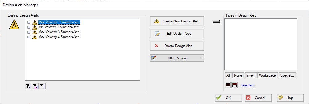
Figure 1: Design Alert Manager
Creating and Applying Design Alerts
Click Create New Design Alert to add a new Design Alert to the model. The Design Alert Manager expands to allow the creation of the new alert.
A Name, Object Type, and at least one Parameter are required. Depending on the Object Type, a different selection of Parameters is available, as shown below. To add a Parameter:
-
Select the desired parameter
-
Select whether this is the maximum or minimum allowable value
-
Enter the value with the appropriate units (if applicable)
-
Click Add to List.
Several Parameter limits can be added to one Design Alert. For example, an alert can be created that requires a pressure within a range by adding both the maximum and minimum pressure limits.
To update a Parameter, simply create it again and click Add to List - the old value will be replaced with the new one.
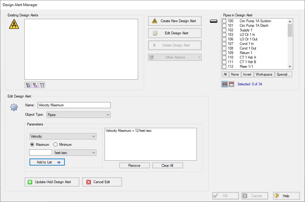
Figure 2: Creating a Design Alert
Table 1: Available Design Alerts
| Pipes | General Junctions | Pump | Valves | Heat Exchangers | Reservoirs |
|
Mass Flow Rate Pressure Gradient Stag. Total Pressure Stagnation Pressure Static Submergence Inlet Margin Submergence Outlet Margin Temperature Stagnation Vapor Pressure Margin Velocity Volumetric Flow Rate |
Gradeline Energy Inlet (EGL) Gradeline Energy Outlet (EGL) Gradeline Hydraulic Inlet (HGL) Gradeline Hydraulic Outlet (HGL) Pressure loss Stagnation Total Pressure Loss Static Total Pressure Stagnation Inlet Pressure Stagnation Outlet Pressure Static Inlet Pressure Static Outlet |
Head Rise Mass Flow Rate NPSH Margin Absolute NPSHA Overall Power Percent of BEP Pressure Discharge Stagnation Pressure Discharge Static Pressure Rise Stagnation Pressure Suction Stagnation Pressure Suction Static Speed Volumetric Flow Rate |
Cv Flow Area Head Loss K Kv Mass Flow Rate Open Percentage Pressure Drop Stagnation Pressure Inlet Static Pressure Outlet Static Volumetric Flow Rate |
Head Loss Heat Rate Log Mean Temperature Difference Mass Flow Rate Pressure Drop Stagnation Temperature Inlet Temperature Outlet Volumetric Flow Rate |
Liquid Height Liquid Surface Elevation Mass of Liquid in Reservoir Volume of Liquid in Reservoir |
At this point, the Design Alert still has not be created. To finalize it, click "Update/Add Design Alert."
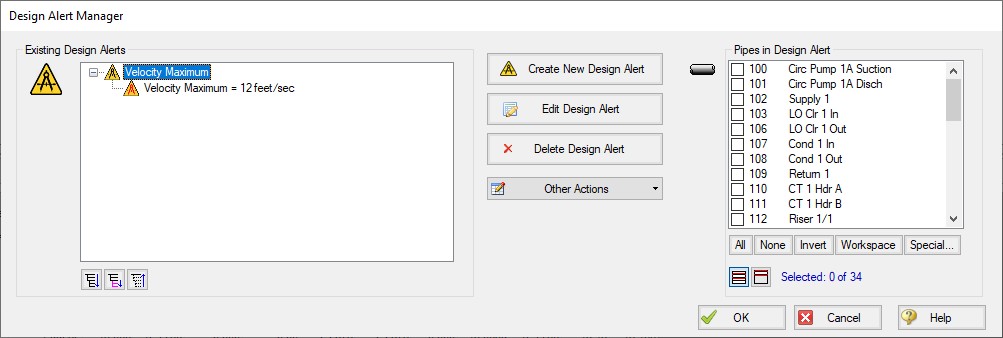
Figure 3: An Existing Design Alert
The Design Alert now exists, but has not yet been applied to any objects in the model. To include objects in the model, select them in the pane on the right.
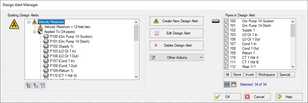
Figure 4: Fully Defined Design Alert
Note that the application of Design Alerts can also be managed for individual objects in their Properties Window's Design Alerts tab.
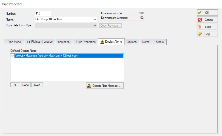
Figure 5: Apply Desired Design Alerts to this Object
When running the model, the selected object's output values will be checked against the limits that have been defined. If any of the Design Alerts are violated, the user will receive a Design Alert warning and the violating parameters will be highlighted in the output tables. Design Alert warnings can be double-clicked to take you to that object in the Workspace.
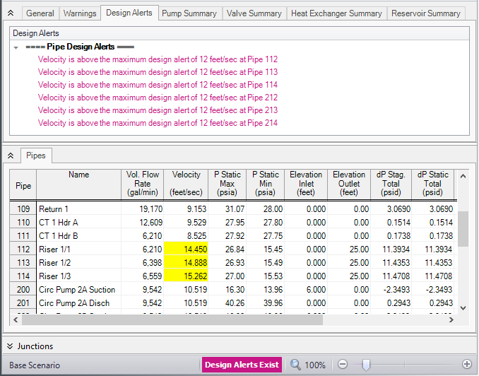
Figure 6: Design Alert Violations in Output
Design alerts are visible in every scenario in a model, but can be turned off or on for specific scenarios. When creating a design alert for the first time it will be active in that scenario and all descendent scenarios. For more information about scenarios, please read the Scenario Manager help topic.


