Cooling System, Multiple Design Cases - ANS (English Units)
Cooling System, Multiple Design Cases - ANS (Metric Units)
Summary
Some pipe system designs have multiple operating conditions to satisfy. For instance, the cooling water example discussed in the previous example may have a requirement that it operate with one of the pumps turned off. This can be modeled in the ANS module by taking advantage of its ability to model multiple systems concurrently.
Note: This example can only be run if you have a license for the ANS module.
Topics Covered
-
Defining dependent Design Cases
-
Using Duplicate Special to create Dependent Designs
-
Specifying fractional pump costs with Dependent Design Cases
-
Using multiple Dependent Design Cases
Required Knowledge
This example assumes the user has already worked through the Walk-Through Examples section, and has a level of knowledge consistent with the topics covered there. If this is not the case, please review the Walk-Through Examples, beginning with the Beginner: Three Reservoir Model example. You can also watch the AFT Fathom Quick Start Video Tutorial Series on the AFT website, as it covers the majority of the topics discussed in the Three-Reservoir Model example.
In addition, it is assumed that the user has worked through the Beginner: Three-Reservoir Problem - ANS example, and is familiar with the basics of ANS analysis.
Since this example is a continuation of the Cooling System - ANS example, it is recommended to complete that example first before beginning this example.
Model Files
This example uses the following files, which are installed in the Examples folder as part of the AFT Fathom installation:
-
Cooling System.dat - engineering library
-
Cooling System Costs.cst - cost library for Cooling System.dat
-
Steel - ANSI Pipe Costs.cst - cost library for Steel - ANSI pipes
Step 1. Start AFT Fathom
From the Start Menu choose the AFT Fathom 12 folder and select AFT Fathom 12.
To ensure that your results are the same as those presented in this documentation, this example should be run using all default AFT Fathom settings, unless you are specifically instructed to do otherwise.
Step 2. Open the model
Open the
Browse to the Life Cycle Cost scenario in Scenario Manager. Create a child scenario from this called Dependent Design Cases to work in for this example.
Step 3. Enable Dependent Design
When modeling multiple design cases, the different cases need to be broken up into a primary design case, of which there is one, and dependent design cases, of which there can be any number.
The primary design case can be any of the design cases that are being addressed in your model. Typically, it will represent the primary operating condition of the pipe system. The dependent design cases represent the same physical operating system, but are used to represent differing operating conditions. If it is not clear which case should be the primary case, just pick any of the cases and call that the primary one. Design cases other than the primary case are referred to as dependent design cases. The reason why we choose a primary case and refer to the other cases as dependent cases will become clearer as we progress through this topic.
For this example the primary design case is the system running with all pumps turned on. We want to also consider the case where only one pump is running. The one pump running case will be created as a dependent design case.
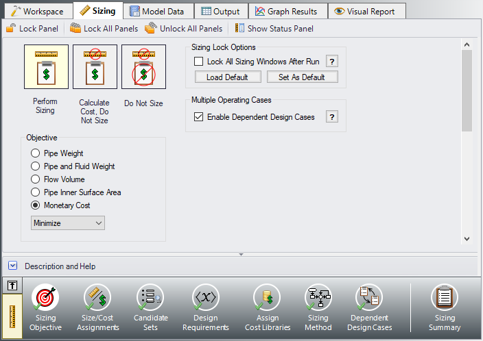
Dependent design case modeling is enabled in the Sizing Objective panel.
ØIn the Dependent Design Case scenario go to the Sizing window and to the Sizing Objective panel. Check the box next to Enable Dependent Design Cases. A new button will now be available for the Dependent Design Cases panel in the Sizing Navigation Panel as shown in Figure 2.
Step 4. Setting up the Dependent Design Case
A. Using Duplicate Special
The easiest way to set up a dependent design case once it has been enabled is to use Duplicate Special, which will allow us to make an exact duplicate of the model in order to setup the additional operating cases. Note that you should fully define the model and all the sizing settings for the primary case before creating the dependent cases, as has been done in this model.
To create the dependent cases:
-
Make sure that the scenario where the dependent cases will be created is loaded. In this case, you should have the Dependent Design Cases scenario loaded.
-
Go to the Workspace.
-
Go to the Edit menu and choose Select All.
-
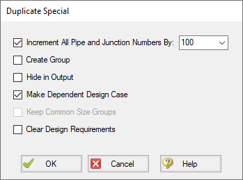
Go to the Edit menu again and choose Duplicate Special (see Figure 3).
-
Choose an increment for the pipe and junction numbers. The number should be large enough to avoid conflicts with numbers used for other pipes and junctions in this and all other scenarios. In this case use 100.
-
Select the Make Dependent Design Case check box.
-
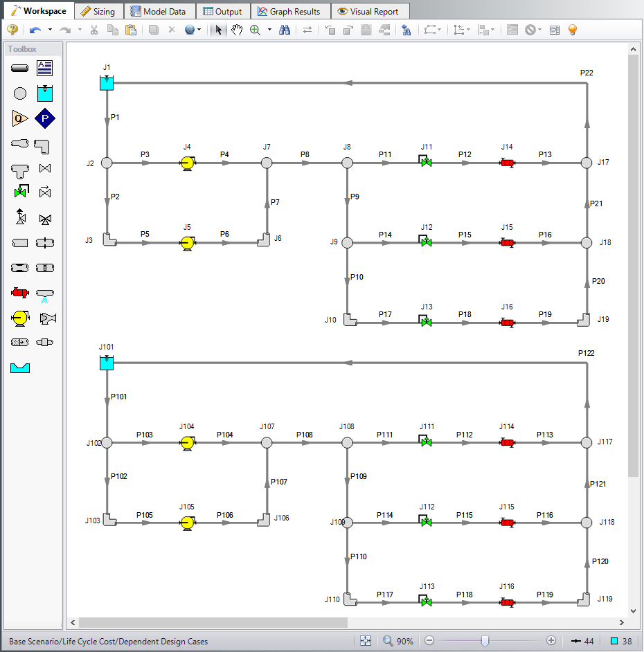
Click OK and move the duplicated version of the primary design case to an open area in the Workspace. The model should now appear similar to Figure 4.
Note that Duplicate Special also allows you to do the following:
-
Create a group for the dependent design case. This can simplify managing the pipe and junction objects in the design case.
-
Hide the pipe and junction in the output. You may want to do this for reasons to be discussed later in this topic.
-
Keep Common Size Groups. This feature is useful when using Duplicate Special for reasons other than dependent case creation, and can't be used when making a dependent design case.
-
Clear the Design Requirements. For reasons to be discussed, frequently dependent design cases will employ different design requirements than the primary design case. This option allows you to clear all the current requirements, so new ones can be assigned.
B. Apply the Dependent Design Operating Conditions
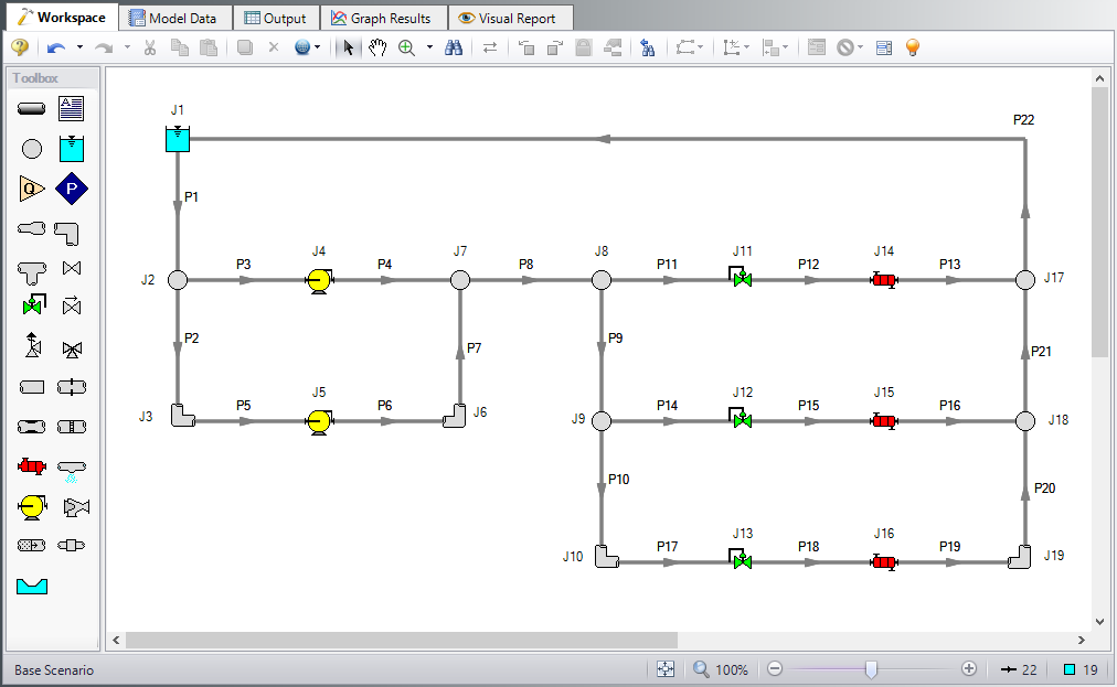
The dependent design case capability takes advantage of the ANS module's ability to run multiple models in the same Workspace. The pipes and junctions in Figure 4 that are numbered greater than 100 (i.e., the dependent design case) represent the same pipes and junctions as those numbered less than 100 (i.e., the primary design case). It is therefore critically important that only certain data in the dependent case is changed.
Frequently the Design Requirements or Special Conditions on the pipes or junctions will be changed. However, data such as a pipe's length or pump's performance should never change. The reason is that once this kind of data is changed, the pipe or junction is no longer the same pipe or junction, and thus the purpose of the dependent link is invalidated. The ANS module does not prevent changing data that should not be changed, but when the model is run it will check to make sure all data that should be the same actually is the same.
In this example we are analyzing the case where one pump in the system is shut off, so we will use Special Conditions on the pump. With one pump shutoff we will not have enough flow to supply all three heat exchangers, so we will also close one of the heat exchangers as well as a control valve.
ØChange the Special Conditions of J105 to Pump Off No Flow.
ØChange the Special Conditions of J111 to Closed.
The dependent case should now appear as shown in Figure 5.
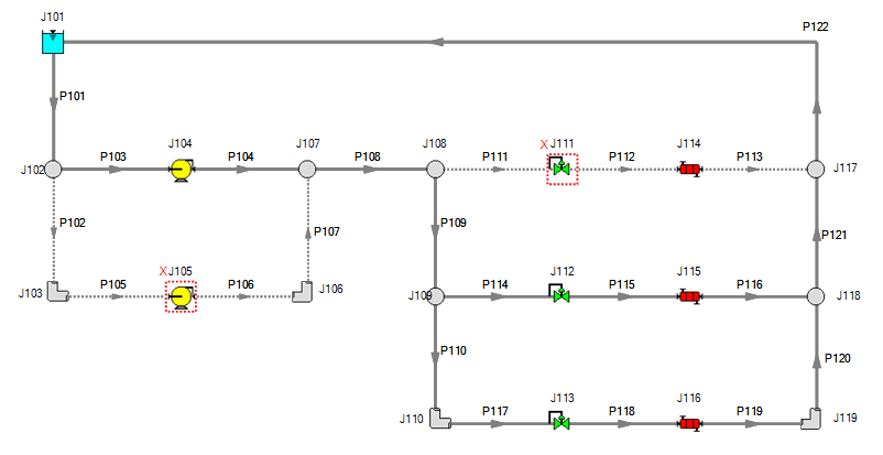
Figure 5: Flow off for Pump 105 and Control Valve 111 in the Dependent Design Case
We will now need to adjust the Design Requirements for the model. Go to the Design Requirements panel on the Sizing window.
Currently it can be seen that Duplicate Special maintained all of the same design requirement applications from the primary case in the dependent case. While most of the design requirements used in the primary case still apply, we will need to remove the Design Requirements from the closed sections of the model. If the model were run without making any changes, the ANS module would not be able to find a feasible system, since it is impossible to achieve a minimum flow of
The flow requirements for Heat Exchanger 115 and 116 will also need to be reconsidered. Since there is only one pump running a lower supply flow rate is expected, so the minimum flow rate required by the coolers should be lowered to
The pressure drop across the control valves still needs to be a minimum of
Apply the changes as follows:
-
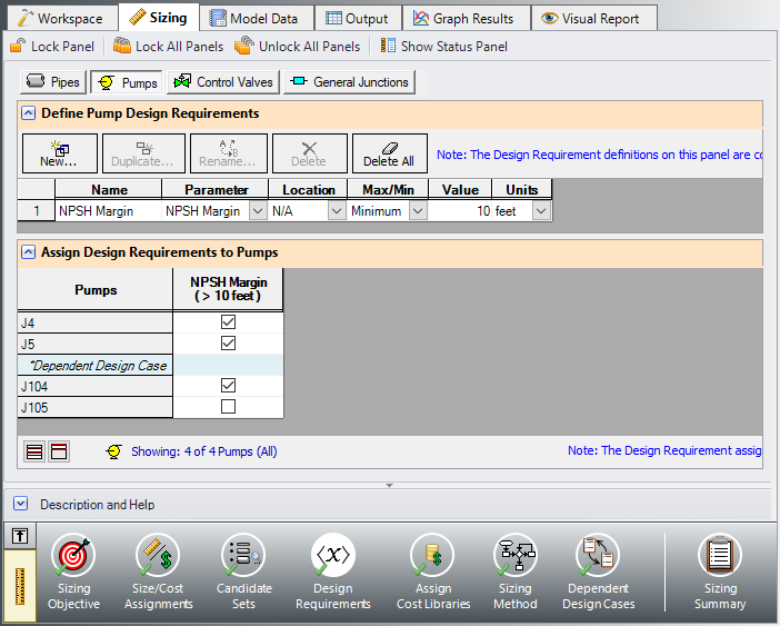
Click the Pumps button to go to the pump Design Requirements
-
Uncheck the box next to J105 to remove the NPSH requirement from Pump 105 in the dependent case (Figure 6).
-
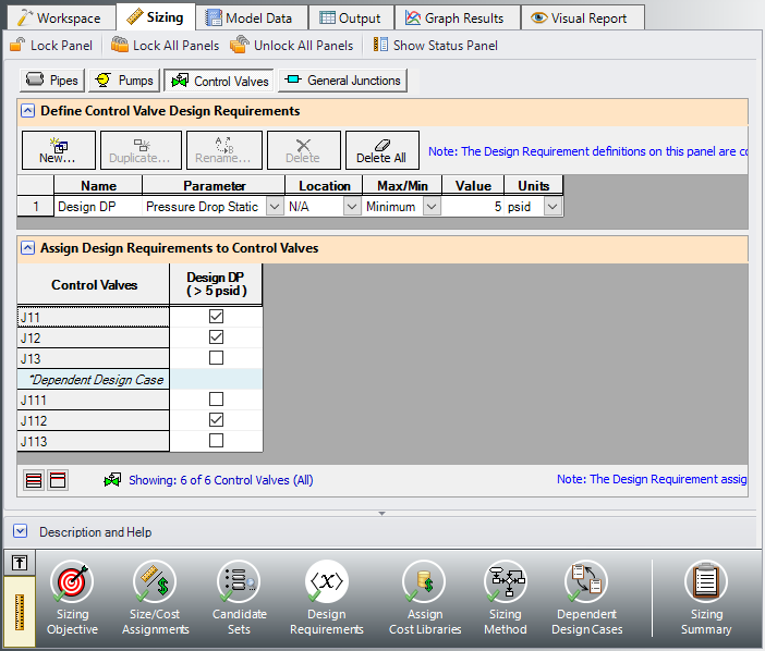
Click the Control Valves button to go to the control valve Design Requirements.
-
Uncheck the box next to J111 to remove the pressure drop requirement from the closed control valve (Figure 7).
-
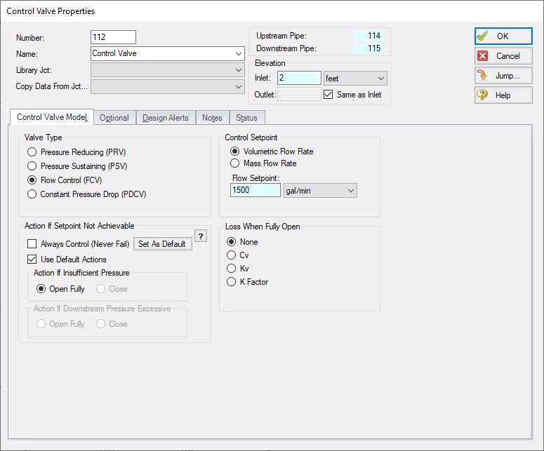
Return to the Workspace and open the Control Valve Properties window for J112.
-
Change the Valve Type of Flow Control (FCV) with a Flow Setpoint of 1500 gal/min (Figure 8).
No other changes are needed, so the Dependent Design Case scenario is now complete.
ØSelect Run from the Analysis menu to perform the automated sizing, and go to the Output window once the run is complete to view the results.
Summary
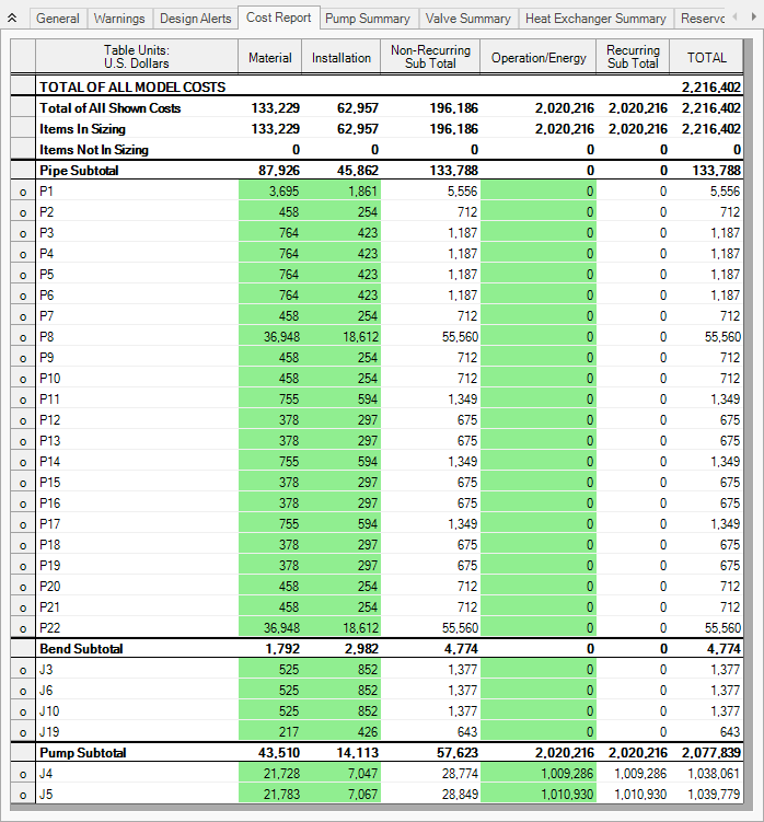
The cost report for the Dependent Design Case scenario can be seen in Figure 9 below.
Note that the pipes and junctions in the dependent case are separate entities for modeling purposes, but represent the same pipes and junctions as the primary case. Thus when performing automated sizing, we only count the cost of the pipes and junctions once. This occurs in the primary design case, which in our model is the two pumps running case. This is why only the primary design case pipes are shown in the cost report.
With one exception, it is not possible for a model that includes a dependent design case to yield a better design than the primary case alone. At best, it can yield the same design, such as in this scenario. This is due to the fact that the dependent design case imposes additional restrictions on the solution by adding additional design requirements. If the design for the primary design case is not sufficient for the dependent design case, then the design must be changed, which will increase cost in some manner.
Turning off Pump 105 in this scenario required no adjustments in the pipe sizes, so the initial sizing results remained unchanged.