Heat Transfer in Pipes
The Heat Transfer tab is only visible when heat transfer is being modeled. Heat transfer modeling is enabled in Analysis Setup on the Heat Transfer/Variable Fluids panel.
Each pipe responds thermally to the environment outside of the pipe. AFT Fathom offers several models that allow you to model the heat transfer characteristics of a pipe:
-
Adiabatic (Perfectly Insulated) - An adiabatic pipe is one that has perfect insulation and thus no heat transfer takes place. This model differs from Isothermal in that the temperature into the pipe is taken from the upstream junction. This is the default model. Insulation data can be entered but is not used for thermal purposes.
-
Isothermal - The Isothermal model maintains the pipe at the specified temperature. Insulation data can be entered but is not used for thermal purposes.
-
Convective Heat Transfer - This model allows you to specify heat transfer data for the internal fluid, pipe wall, three layers of insulation and external convection.
-
Convective Heat Transfer and Heat Flux - This model allows you to model convective heat transfer while also specifying a constant heat flux.
-
Convective Heat Transfer with Heat Tracing - This represents adding some type of heating layer onto the pipe's outer surface. The amount of heating may be entered as a constant heat flux or by providing information on the power and number of wire turns. Insulation layers can then be added on top of the heat tracing (heat flux source).
-
Constant Heat Flux - The constant heat flux model is useful in cases where the temperature difference between the fluid and the ambient environment is extremely large or in cases where a large radiant heat flux exists. Insulation data can be entered but is not used for thermal purposes.
-
Constant Heat Rate – This model allows you to specify a constant heat rate into or out of the pipe.
-
Buried Pipe - This model allows you to specify that the pipe is buried in a thermally conductive medium.
Note that similar to flow rate definition, heat flow is positive when flowing into the pipe, and negative when flowing out.
Viewing Calculated Thermal Results in Output
A table is displayed in the Output window Pipe area showing the temperature distribution in the pipe and insulation.
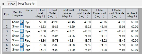
Figure 1: Thermal Data table in Output window Pipe area shows temperature distribution in pipe
Clicking the button next to Show brings up a Results Diagram for that particular pipe:
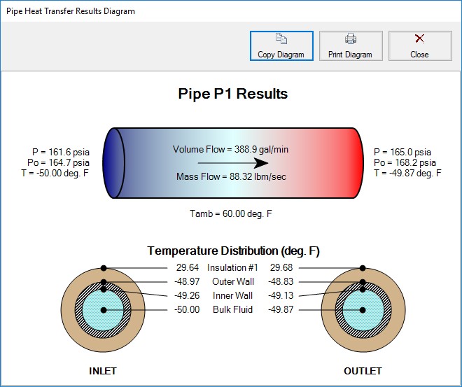
Figure 2: Pipe Heat Transfer Results Diagram
Related Blogs
Let the Heat Flow: Modeling Heat Transfer in Pipes in AFT Fathom and AFT Arrow


