Interstage Bleed/Takeoff Flow
Some multiple stage pumps can have flow removed at some intermediate point. For such pumps, the manufacturer provides two pump curves:
-
Overall Pump Curve - The total dynamic head from the suction of the first stage to the discharge of the last stage when the takeoff flow is zero.
-
Takeoff Pump Curve - The total dynamic head of the stages before the takeoff point.
Note: The Overall Pump Curve is an effective curve that describes the operation of all pump stages together. This curve cannot be directly used to determine the overall head when the takeoff flow is anything other than zero.
Defining the Model
First, place two pump junctions onto the Workspace, representing the upstream and downstream stages of the multistage pump.
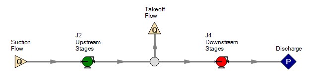
Figure 1: Example Workspace layout - color for emphasis only
Both pumps need to be defined as "Interstage Bleed/Takeoff Flow" as shown below. The "Upstream Stages" pump should have the Takeoff Curve entered. The "Downstream Stages" pump should have the Overall Pump Curve entered.
Keep in mind that the pipes connecting the two pumps do not exist in reality. For this reason, it is reasonable to make these pipes have as little impact as possible. This can be done by making them short and/or frictionless. Otherwise, there will be some nominal frictional head loss in the section where effectively none would exist in the real system.
Additionally, the two pumps need to be "connected" by setting the junction of the corresponding pump junction in this area.
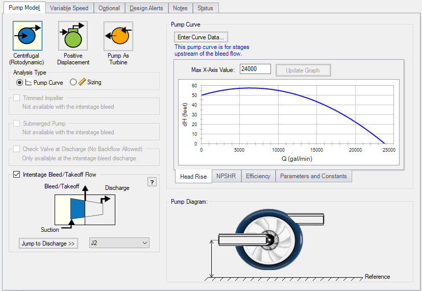
Figure 2: Interstage Configuration
Methodology
As can be seen in Figure 3, the Suction Flow is always equal to the sum of the Takeoff and Discharge Flows. Also important to note is that the Suction Flow is always equal to the discharge flow of the upstream stages - that is, adjusting the takeoff flow does not directly affect the behavior of the upstream stages.
From this, we can determine the head that is added by the upstream stages by examining the Takeoff Pump Curve at the Suction Flow. This is shown in Figure 4 as Upstream Stages Head.
Next, we need to determine the head contributed by the Downstream Stages. However, we do not know the pump curve for these stages! By subtracting the Takeoff Pump Curve from the Overall Pump Curve, we can determine the Downstream Stages Pump Curve. Knowing the Discharge Flow (Suction Flow - Takeoff Flow), we can now look up the Downstream Stages Head, as shown in Figure 4.
Adding these two values brings us to the Overall Effective head across the entire pump at the given Discharge Flow. This value will be smaller than the Overall Pump Curve value due to the head lost to the Takeoff Flow.
Similarly, adding the overall power calculated at each of the pump junctions will give the ideal Overall Effective power for the entire pump.
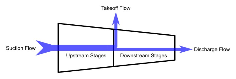
Figure 3: Interstage Diagram
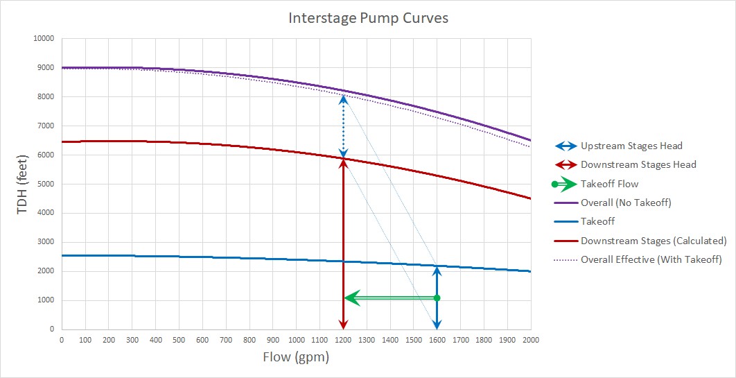
Figure 4: Interstage Curves
Related Topics
Related Blogs
Not a Leak! Modeling Multi-stage Pumps with Discharge Flow Between Stages


