Four Quadrant Zones of Operation
While a turbomachine can operate anywhere in the four quadrants of the speed-flow plane, it will only act as a pump in certain areas. It can also act as a turbine, or be in an "energy dissipation" zone.
The behavior of a pump changes significantly depending on its design - a radial (low specific speed) pump has different characteristics than an axial (high specific speed) pump.
Zones of Operation
-
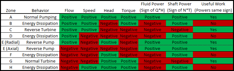
Zone A - Normal Pumping - This is the region represented by a Standard Pump Curve, generally available from the manufacturer. Energy is transferred from the driver to the fluid, imposing flow and positive head.
-
Zone B - Energy Dissipation - Region exceeding maximum pump flow (or runout flow). Head is lost across the pump.
-
Zone C - Reverse Turbine - Flow and speed are in the positive direction, driving the shaft. This is termed "reverse" because it is typical for turbines to run in the opposite direction.
-
Zone D - Energy Dissipation - Energy entering the system is actively opposing the natural flow direction.
-
Zone E - Reverse Pump - The impeller is rotating backwards, but pumping action is still taking place. Energy is transferred from the driver to the fluid, imposing flow and head. The behavior of this zone varies based on design - radial designs can still pump in the normal direction when rotating backwards, whereas axial machines can force the flow in the reverse direction.
-
Zone F - Energy Dissipation - The impeller is rotating backwards, with negative flow. However, head is increased. This zone is similar to Zone B.
-
Zone G - Normal Turbine - Flow and speed are in the reverse direction, driving the shaft, causing the machine to generate power.
-
Zone H - Energy Dissipation - Energy entering the system is actively opposing the natural flow direction. This zone is similar to Zone D.
Table 1: Characteristics of Zones
Transient Behavior
The operation of a pump must move continuously from one point on the speed-flow plane to another. It can never "jump" to an entirely different zone.
For example, consider a pump lifting fluid over a hill under a trip event.
The pump will initially be operating in Zone A, but under loss of driver torque will immediately begin to change speed and flow.
The inertia of the device will maintain forward speed while flow reverses - in other words, the Zone will change from A to H. The energy dissipation Zone H is unstable - the act of reverse flow on the forward rotating impeller with no applied torque will slow the impeller down and eventually reverse its direction.
Once speed direction changes, the pump is now operating in Zone G. Energy could theoretically be extracted in this turbine zone, however, there is no connected driver. The energy from the still positive torque must go somewhere - into speeding up the impeller.
At some point, the impeller will speed up enough that operation crosses into Zone F. In Zone F, the torque changes sign - causing the impeller to slow down and return to Zone G. The device will oscillate around the zero torque line, eventually coming to a new steady-state - runaway conditions.
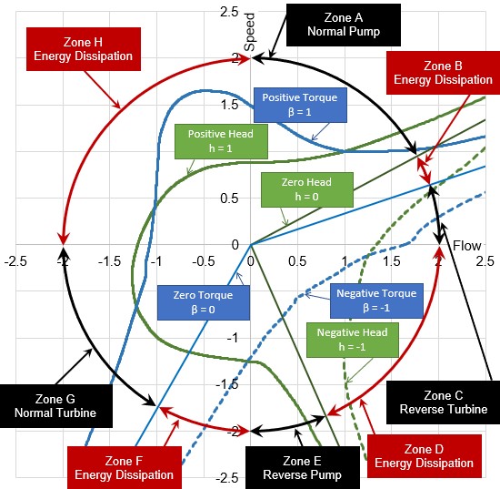
Figure 2: Zones of operation for a radial design pump, from data set Ns = 1800 gpm (34.9 m3/s)


