Design Alerts
Design Alerts are a powerful feature that can help speed up the modeling process and help verify that the model is behaving as expected. Design Alerts provide easy identification of output parameters that exceed specified limits for a variety of different parameters for both pipes and junctions. The creation of a Design Alert does not constrain or affect the operation of the model in any way. However, it automatically creates an output alert any time the design limit is violated. One common use case might be defining a maximum allowable pressure for the pipes in the model. While the output can be reviewed manually for these violations, this quickly becomes tedious as the model grows in size. Creating a Design Alert instead allows the engineer to spend less time reviewing output tables as any violation will be immediately identified.
The Design Alert Manager allows the user to create or modify Design Alerts. It can be accessed from the Tools Menu, the Design Alerts tab in pipe and junction properties windows, or from the Design Alert Layer Settings window.
Design Alerts can also be created directly from the output, or can be imported/exported for use in other models.
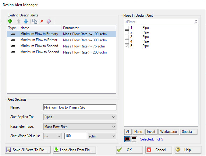
Figure 1: Design Alert Manager
Creating and Applying Design Alerts
Click the green plus sign (New Design Alert) to add a new Design Alert to the model.
A Name, Object Type, and Parameter Type and Value can be specified. Depending on the Object Type, a different selection of Parameters are available, as shown below. To add a Parameter:
-
Give the Design Alert a distinct and descriptive name.
-
Select the Object Type the alert will be applied to.
-
Select the Parameter Type the alter will monitor.
-
Specify a value, unit if applicable, and companion.
-
Use >= when the value shouldn't rise above the specified value (i.e. temperature shouldn't exceed a maximum value)
-
Use <= when the value shouldn't fall below the specified value (i.e. pressure shouldn't drop below a minimum value)
-
Select which Objects from the Workspace the Design Alert will be applied to.
-
Click "OK" to save changes.
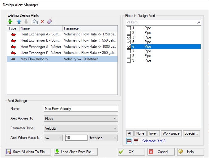
Figure 2: Creating a Design Alert
Table 1: Available Design Alerts
| Pipes | General Junctions | Compressors/Fans | Valves | Heat Exchangers | Forces |
|---|---|---|---|---|---|
|
Enthalpy Stagnation Enthalpy Static Mach Number Mass Flow Rate Pressure Stagnation Pressure Static Temperature Stagnation Temperature Static Velocity Vol. Flow Rate |
Pressure Loss Stagnation Total Pressure Loss Static Total Pressure Stagnation Inlet Pressure Stagnation Outlet Pressure Static Inlet Pressure Static Outlet |
Mass Flow Rate Pressure Discharge Stagnation Pressure Discharge Static Pressure Rise Static Pressure Suction Stagnation Pressure Suction Static Speed |
Cv Flow Area K Kv Mass Flow Rate Open Percentage Pressure Drop Stagnation Pressure Static Inlet Pressure Static Outlet |
Mass Flow Rate Pressure Drop Static Temperature Inlet Static Temperature Outlet Static |
Maximum Absolute Force Maximum Negative Force Maximum Positive Force |
Once a Design Alert has been created, it can also be applied from within the pipe and junction properties window under the Design Alerts tab. A list of available Design Alerts will be shown in the properties window and can be selected to be applied to the pipe or junction.
Design alerts are defined globally but must be applied to pipes and junctions on an individual basis in each scenario. Design Alerts will be visible in all scenarios but will only be evaluated if the Design Alert is applied to a pipe or junction in the current scenario. Applying Design Alerts to pipes and junctions follows standard scenario inheritance rules.
When running the model, the selected object's output values will be checked against the conditions that have been defined. If any of the Design Alert conditions are met, the user will receive a Design Alert warning on the Design Alerts tab in the general output section, and the violating parameters will be highlighted in the Output tables. Design Alert warnings can be double-clicked to take you to that object in the Workspace.
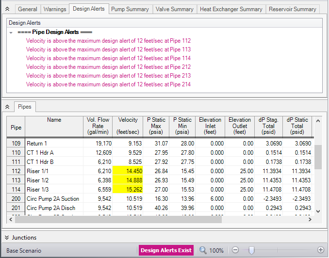
Figure 3: Design Alert Violations in Output
Design Alerts can be cross-plotted on most Graph Types vs. the actual results by checking the box in the "DA" column of the Graph Parameters. However, you must be graphing the same parameter for which the Design Alert was created, otherwise the check box will do nothing. For example, if you created a Design Alert for static pressure, you must add the Pressure Static graph parameter and check the box for DA next to it. If applicable, the Design Alert will graph a constant line at the specified value, and you can see where your parameter rises or falls below it. The Design Alert will display as a separate legend entry on the graph and can be toggled on or off.
Design Alerts can also be evaluated directly on the Workspace through Workspace Layers. The Design Alert Layer will display applied and violated Design Alerts directly on the model for quick visualization of areas within a piping network that are operating outside of specified limits. The Workspace will be color coded to visualize this information. For more information, visit the Design Alert Layer topic.