New in Version 3
View the links below for key updates from past versions:
Workspace Layers
The Workspace Layers feature provides a powerful new tool for customizing and viewing model appearance, input data, and results - all in one place. The Workspace Layers toolset significantly enhances the model building process, providing unparalleled customization options. You can easily update pipe/junction size, color, display text, visibility, and more from a centralized location on the Quick Access Panel. Workspace Layers surpass the capabilities of the previous Visual Report feature. With Layer Settings, you now have easy control over Color Mapping and the visibility of both Input and Output parameters. Any change you make to these settings will have an immediate impact on the model’s display, providing real-time feedback. The dynamic combination of unique Layers offers an incredibly flexible framework, allowing you to display precisely what you desire on the Workspace. You can easily toggle the visibility of individual layers on or off, and the state of all layers can be saved to a Layer Preset for future use.
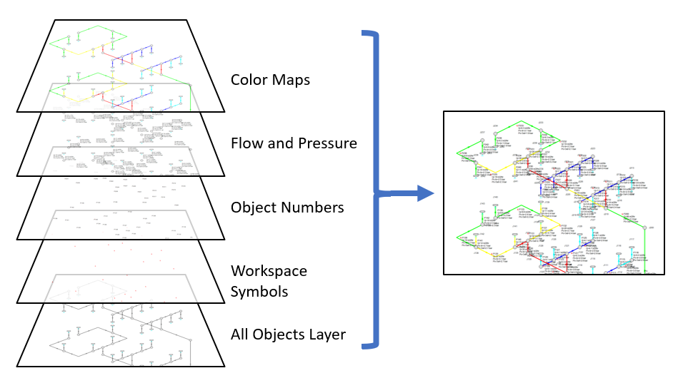
Figure 1: Workspace Layers can display input and output values superimposed over the model, show Color Maps, and control visibility of objects
Reciprocating Compressors
Model single or double-acting multi-cylinder reciprocating compressors, accounting fully for all fundamental thermodynamics. Completely new in this version of AFT xStream is a fully transient reciprocating compressor model that considers the thermodynamic effects of gas being compressed or expanded in a closed chamber. Combined with the fundamental gas dynamics considered by the AFT xStream transient solver, this offers an exceptionally powerful simulation tool. The reciprocating compressor model offers the flexibility to specify single or double-acting compressors, with various arrangements including opposed, inline, or V configurations, accommodating up to six cylinders. The model incorporates a physical representation of the cylinder geometry and valve opening crank angles. In combination with the PFA module improvements in this version, this enables engineers to analyze the pulsation effects of reciprocating compressor systems with greater precision and confidence.
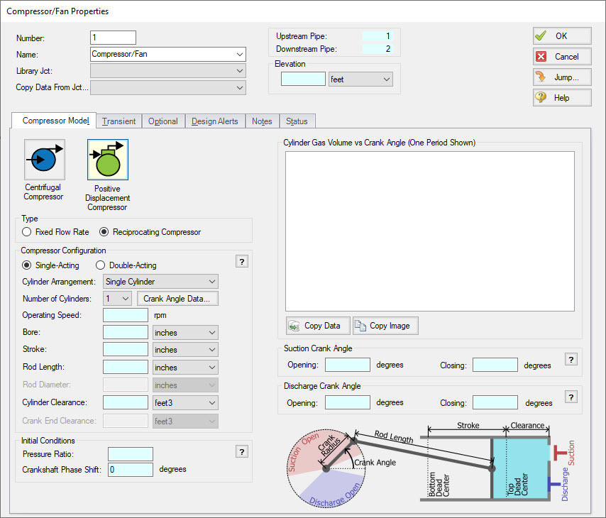
Figure 2: Reciprocating Compressors can be modeled inside the Compressor Properties menu under the Positive Displacement option
Transient Checkpoints
Extend the length of an existing transient run without the need to re-run the entire simulation, or stop and continue a run from other points in the simulation. Transient Checkpoints enable you to save the state of a transient simulation at any given point and resume it later from that exact point. This functionality proves particularly useful in scenarios where you need to pause a simulation temporarily to provide access to another user or when unexpected interruptions, such as system updates, occur during the simulation. This feature also allows for the extension of a transient run. If you have ever experienced the frustration of waiting for results only to realize that you should have run the simulation for a slightly longer duration, this feature provides a solution. Instead of rerunning the entire simulation, you can simply extend an existing run by leveraging the automatically created Transient Checkpoints.
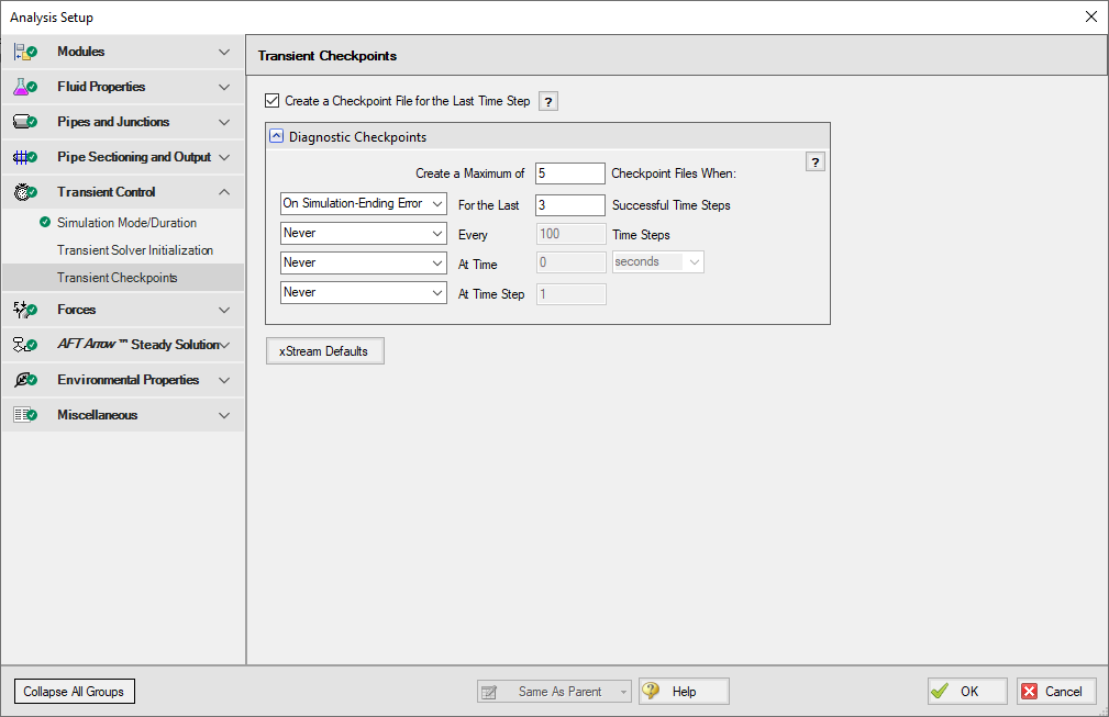
Figure 3: The Transient Checkpoint panel within Analysis Setup
Retain Partial Transient Output
If the simulation is stopped - by the user or an error - show the transient results up to that point. Transient Output is now saved and viewable regardless of what caused the simulation to stop. This means that you can access and analyze the results up to the point where the simulation was interrupted, just like regular results. This eliminates a lot of guesswork involved in interpreting system behavior when it deviates from expectations, particularly when troubleshooting simulation errors. For instance, if a simulation encounters difficulties in converging on a compressor solution due to factors like reverse flow or unexpectedly low temperatures, the availability of partial output enables you to quickly identify these situations. You can then take appropriate corrective measures or provide our Support Team with detailed information to expedite problem resolution.
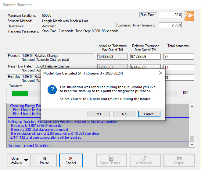
Figure 4: Transient Output can be retained on errors or cancel
Improved Valve Properties Window
The new Valve Properties window greatly enhances clarity and usability when it comes to modeling valves. The window now clearly distinguishes between different data sources such as User Specified, Characteristic, or Handbook, making it easier to understand the available options. The form has been streamlined to focus on the most essential data, providing a clear understanding of what is required to define a valve accurately. Valve Characteristics, represented by an Open Percent vs. Flow Coefficient table, have been brought front and center. While using a Characteristic is optional, it is highly recommended as it ensures that the valve behavior aligns with real-world scenarios, particularly for valve transients. The process of selecting a pre-defined Characteristic Source has been simplified, which helps obtain more accurate values in case manufacturer data is unavailable.
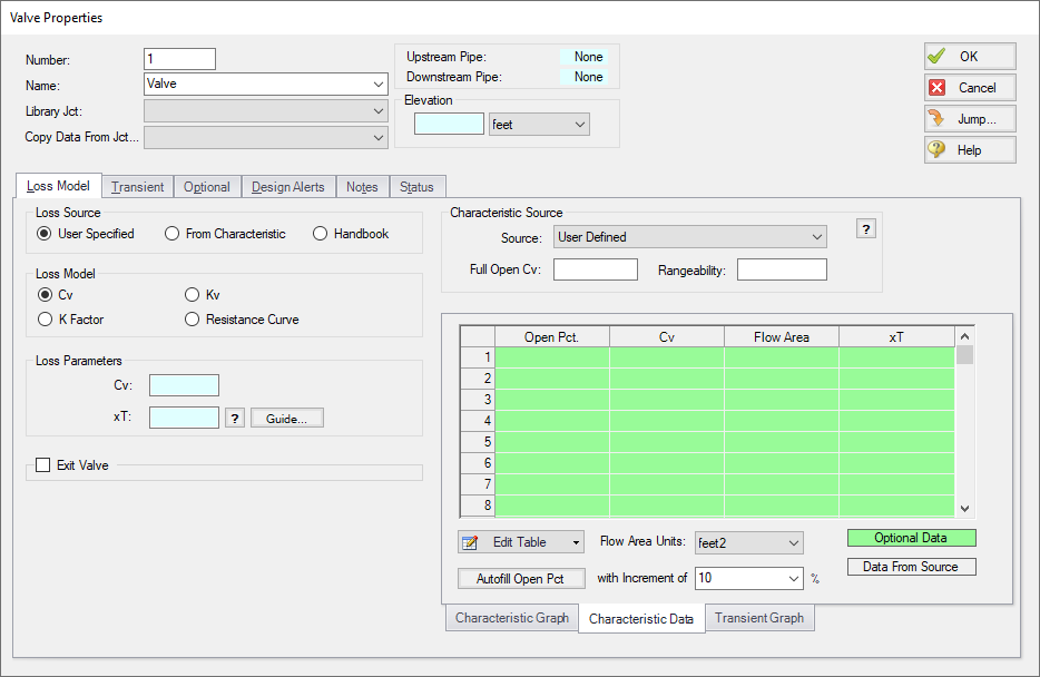
Figure 5: Redesigned Valve Properties window
Streamlined Design Alerts
The Design Alert Manager has been reorganized to improve the process of creating and applying user-defined alerts. Now, you can effortlessly create or edit a Design Alert with just a few clicks. As you modify settings, you will immediately see the criteria you are applying, ensuring a transparent experience. We have also reduced the amount of text on the form, while ensuring grammatical clarity. These improvements aim to make it easier to understand the limits being placed on the design.
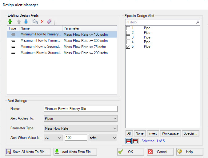
Figure 6: Steamlined Design Alerts Manager
Other Notable Features
-
Custom Junction Icons - Use your own images for junction icons.
Utilize any image as a junction icon, simply by right-clicking on the Toolbox icon for the junction, selecting Add Image, and browsing to the image file. This functionality enables you to use standard P&ID icons or custom images to visually represent your equipment. By using recognizable icons, you can improve the clarity and comprehension of model results, especially for those who may not be familiar with the default AFT junction icons.
![]()
Figure 7: The Customize Icon window allows a custom image to be applied to any junction
-
Isometric Freeform Drawing Mode - Draw on the isometric grid without forcing any particular pipe routing.
The Isometric drawing tools have been enhanced by adding a new Isometric Freeform drawing mode. This new drawing mode allows you to snap junction and pipe anchors to the Isometric grid, while having the flexibility to draw pipes that do not necessarily align with the isometric gridlines. This allows you to easily draw complex systems where not all piping follows a Cartesian direction.

Figure 8: Isometric Freeform drawing mode does not force pipes to follow gridlines
-
New Annotations - There are new shapes and a line tool, along with a more advanced Annotation editing panel.
New Annotation shapes and a line tool have been introduced to allow more flexible markup such as revision numbers or change requests. Editing of Annotations has been revamped with the introduction of a live-edit Quick Access Panel, which provides immediate visual feedback of the changes you make, and simple global editing of all selected Annotations. The new edit panel also offers expanded functionality, providing you with more customization than was possible in the past.
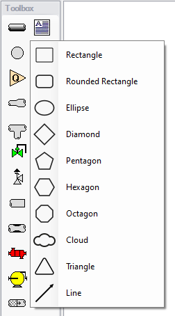
Figure 9: New Annotation options
-
Set Workspace Print Area - Show printing page borders on the Workspace and customize the printing area.
The new Printer Page Layout tool offers a convenient and effortless way to adjust the printing area according to your preferences. With a clear and intuitive visual representation, you can easily identify where page breaks will occur. Now, you can confidently print a specific section or the entire model at your desired scale, eliminating the need for trial and error.
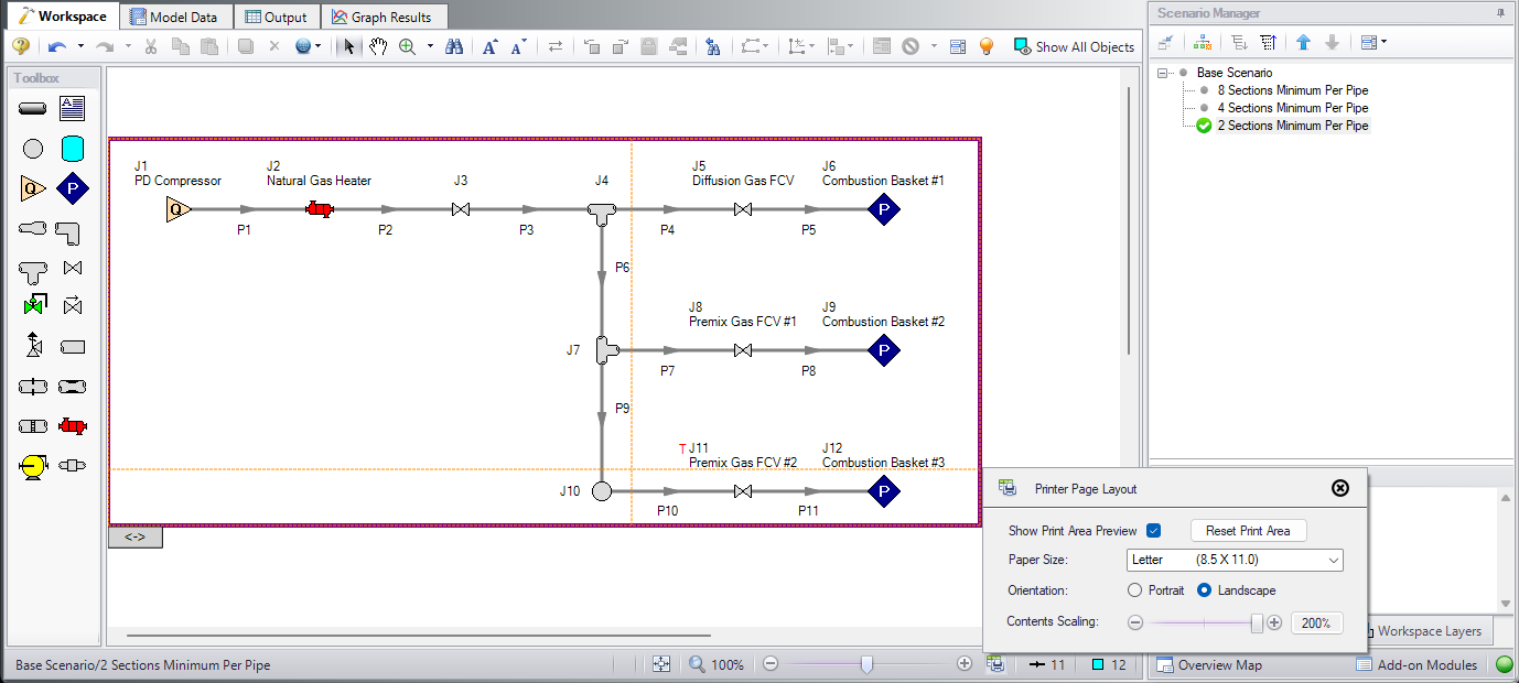
Figure 10: The Printer Page Layout feature allows the user to set the Workspace print area
-
Customize Parameters Available to Graph from the Workspace - New User Options allow custom selection of any graph parameter on the right-click Workspace context menu.
Did you know you can easily graph results from the Workspace by right-clicking on a pipe or junction? This functionality has existed for a long time, but it was previously limited to a predefined set of parameters. Now, you can specify what graph types you would like to see in these menus to simplify your analysis process.
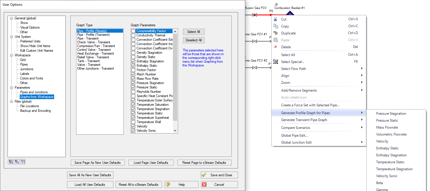
Figure 11: The right-click context menu for pipes on the Workspace can have the graphing parameter options modified
-
PFA Module Improvements - The PFA module has an improved interface, and can now find a Steady State Pulsation solution, allowing better analysis of pulsating systems.
The PFA module interface for xStream has been overhauled to enhance clarity and streamline the process, while introducing new tools essential for pulsation analysis. Chief among these is the addition of a Steady State Pulsation mode, which allows the transient simulation to run until standing waves are formed by the device causing pulsation. This new mode eliminates artificial transients that could affect the accuracy of conclusions drawn from a pulsation study. By focusing on the formation of standing waves, the modal analysis becomes more precise and reliable.
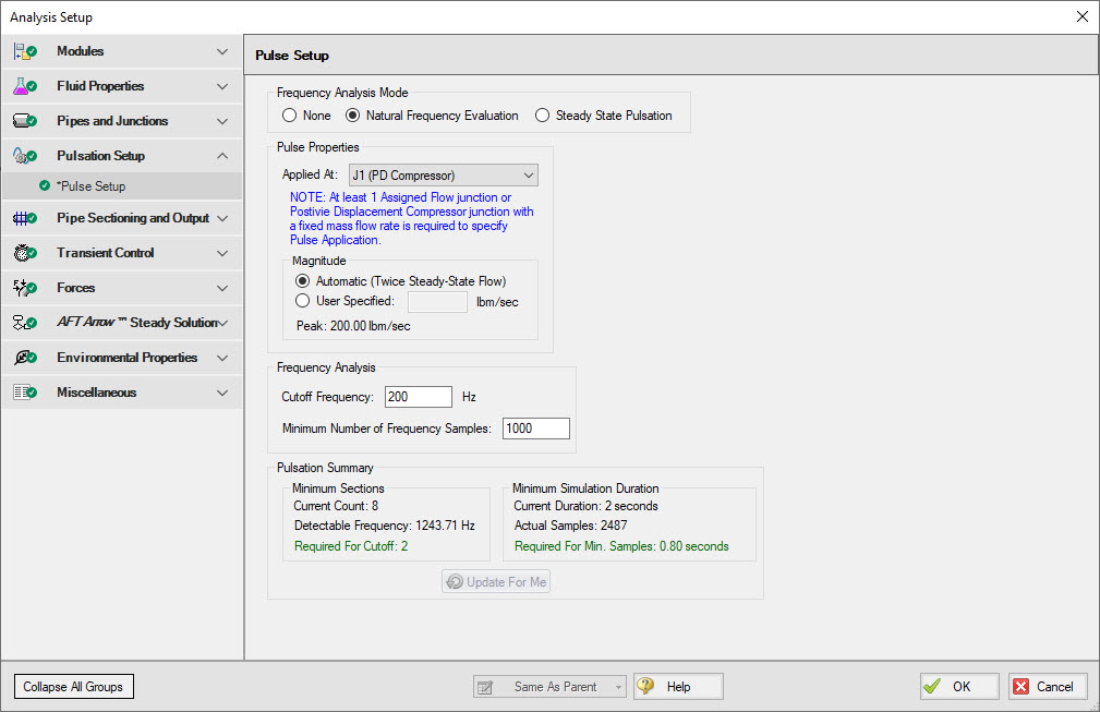
Figure 12: The Pulse Setup panel inside Analysis Setup
Miscellaneous Improvements
-
Modeling Additions and Improvements
-
Fluid Libraries - New category for user-defined fluids, making it easier to find custom entries.
-
Simpler Force Definitions - Difference forces spanning more than 2 pipes no longer require the definition of a group.
-
Control Valve Fully Open Cannot Regain Control - New special condition that keeps the control valve in a locked-open position during transients.
-
API 618 Limitations in PFA Module - API 618 outlines frequency-dependent pulsation limits - you can now check for violations graphically, and see locations where the limit is exceeded.
-
-
Importing of PCF, EPANET, GIS, and CEASAR II Models
-
Bend r/D - Import PCF bends with appropriate r/D values.
-
Speed Increase - Importing is up to 10x faster in some cases.
-
Defaults and Display - Better defaults and display options for imported models.
-
Pipe Materials - Improved ability to link AFT pipe materials to imported pipes.
-
CEASAR II Node Names - Display imported CAESAR II node names as junction names.
-
-
Behind the Scenes Improvements
-
Graphing Optimization - Significant improvements to backend graphing code which provides additional stability now and more capabilities in the future.
-
eLicense Access Improvements - Added a "heartbeat" functionality to eLicenses which improves security and the release of license seats not in use.
-
Output - Significant improvements to backend output code which provides additional stability now and more capabilities in the future.
-
Timed Recovery File - Automatically generate a backup of your unsaved model that can be used to recover unsaved work in the event of unexpected application closure. This is separate from the *.bak files which are only generated after saving a model.
-
-
New and Improved Output Parameters and Messages
-
Compressor RPM Output Parameter Report compressor speed in RPM, in addition to percent.
-
Dimensionless Heat Transfer Parameters - Grashof, Nusselt, Prandtl, and Rayleigh Numbers have been added as Output parameters.
-
Valve xT Output Parameter - Report and graph the xT value used for valves.
-
Estimated xT Output Parameter - Graph saturation temperature and temperature above saturation (superheat) along flow paths.
-
Laminar Caution - Alerts the user if flow at junctions is in a laminar range.
-
Profile Graphs for Temperature Saturation and Temperature Superheat - Graph saturation temperature and temperature above saturation (superheat) along flow paths.
-
Events Messages in New Format - Events are now shown in a cleaner, collapsible format similar to Warnings.
-


